Chain stopping device and windlass

A windlass and chain stop technology, which is applied in the direction of anchor arrangement, transportation and packaging, anchor treatment/binding, etc. It can solve the problems of large force between the chain stopper and the anchor chain ring, occupying space, damage to the anchor chain, etc., and achieves saving effect of space

Active Publication Date: 2014-02-26
WUHAN MARINE MACHINERY PLANT
View PDF4 Cites 12 Cited by
  • Summary
  • Abstract
  • Description
  • Claims
  • Application Information

AI Technical Summary

Problems solved by technology

[0005] The base of the chain stopper is welded on the deck (or in the cabin), occupying the space on the deck (or cabin); when the chain stopper blocks the anchor chain, it directly contacts the anc

Method used


Image

  • Chain stopping device and windlass
  • Chain stopping device and windlass
  • Chain stopping device and windlass

Examples


Embodiment 1

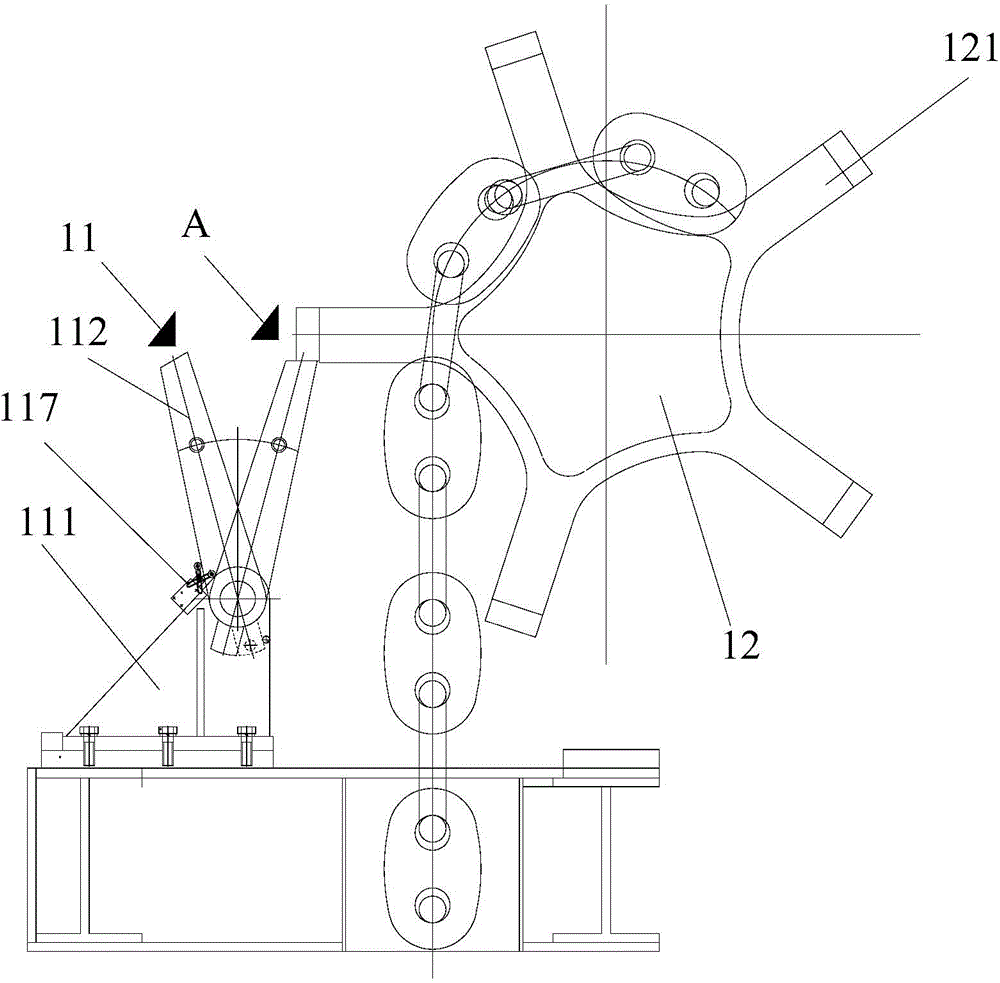
[0032] The embodiment of the present invention provides a chain stop device, see figure 1 , the device comprises: a chain stopper 11 and a chain wheel 12 rotatably mounted on the windlass frame.

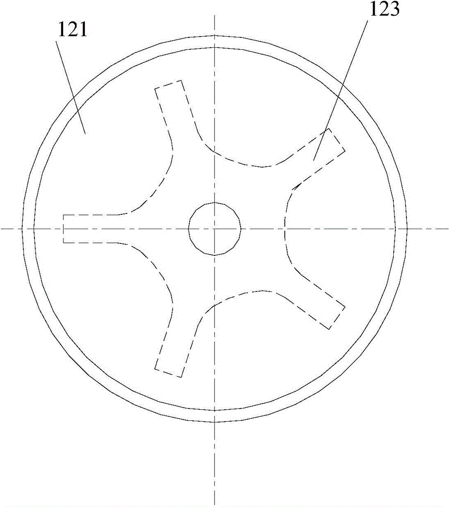
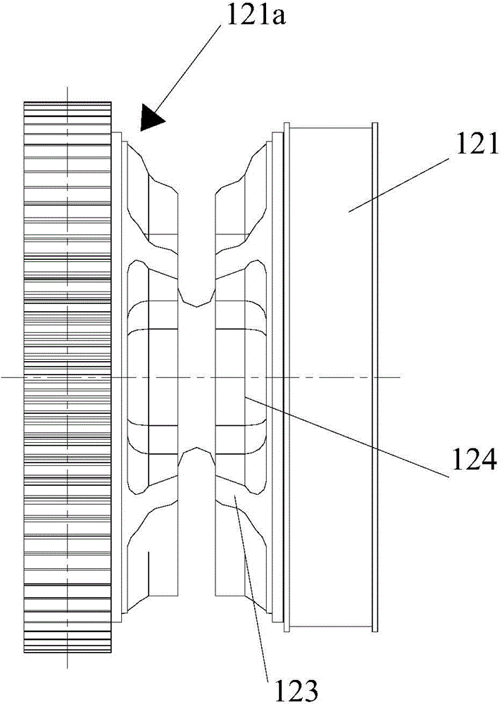
[0033] Such as Figure 2a and Figure 2b As shown, the chain wheel 12 includes two chain wheel plates 121 arranged in parallel and a connecting shaft 122 connecting the two chain wheel plates. The connecting shaft 122 is provided with a groove 124 matching the anchor chain, and when the anchor chain is wound on the anchor wheel, the anchor chain ring rests in the groove 124 . In order to facilitate understanding of the embodiments of the present invention, figure 1 The structure of the anchor chain wheel plate and the connecting shaft of the anchor chain wheel is omitted in the figure.

[0034] In this embodiment, the two anchor chain wheel plates 121 are respectively provided with a plurality of claws 123, and the claws 123 on each anchor chain wheel plate 121 are arranged at in...

Embodiment 2

[0050] The embodiment of the present invention also provides a windlass, which includes a windlass frame, a driving device, a roller, a chain stop device, an anchor chain and an anchor. The drum is rotatably mounted on the windlass frame, the chain stop device is installed on the windlass frame, the anchor chain is wound on the drum and passes around the chain wheel, and the anchor is connected to one end of the anchor chain. The chain stopping device is the chain stopping device provided in the first embodiment.

[0051] In this embodiment, the chain stop device can be installed on the windlass frame by using bolts, or the chain stop device can be directly welded on the windlass frame.

[0052] Optionally, the windlass also includes a braking device for braking the drum.

[0053] When anchoring and anchoring are needed, the stop arm is pushed back to the anchor chain wheel, so that the chain stopper is in the open state of the chain stopper, and the windlass can normally rec...


PUM


Abstract

The invention discloses a chain stopping device and a windlass, and belongs to the technical field of anchor moored positioning of ships and offshore platforms. The chain stopping device comprises a chain stopper and an anchor chain wheel rotatably mounted on a frame of the windlass, the anchor chain wheel is provided with a plurality of claws along the circumferential direction of the anchor chain wheel at intervals, the chain stopper comprises a base and a stop arm, the base is mounted on the frame of the windlass, the stop arm is movably mounted on the base and mutually matched with the claws, and one end of the stop arm is abutted to one of the claws when the stop arm is positioned at a first movable position, so that the anchor chain wheel keeps static. The claws of the anchor chain wheel of the windlass are retained by the chain stopper, so that the anchor chain wheel is static, and an anchor chain is stopped. The chain stopper directly contacts with the claws of the anchor chain wheel instead of contacting with the anchor chain, so that the anchor chain cannot be damaged. The chain stopper is directly mounted on the frame of the windlass and not fixed on a deck (or in a cabin), so that the space of the deck (or the cabin) can be saved.

Description

technical field [0001] The invention relates to the technical field of anchoring and positioning of ships and ocean platforms, in particular to a chain stop device and a windlass. Background technique [0002] When a ship or offshore platform is positioned on a river, lake or sea, the anchor chain (mooring line) will bear a certain tension due to the buoyancy of the ship or offshore platform itself. On the one hand, because the pulling force of the anchor chain acts on the brake belt of the windlass, the huge pressure on the windlass will cause continuous wear of the brake belt; on the other hand, when the braking force of the windlass is less than the huge pulling force of the anchor chain , the anchor chain wheel will rotate under the tension of the anchor chain. At this time, the pretension of the anchor chain will decrease, and the ship or offshore platform will have a large displacement under the action of wind, waves and current. When the displacement When the permiss...

Claims


Application Information

Patent Timeline
IPC IPC(8): B63B21/22B63B21/18B63B21/50
Inventor 刘发展陈云节陈离杨阳
Owner WUHAN MARINE MACHINERY PLANT
Why Eureka
Try Eureka