A variable emergency isolation belt

A barrier and variable technology, applied in the direction of roads, road safety devices, roads, etc., can solve the problems of low standardization, long continuous mileage, strong collision force, etc., achieve high standardization, ease traffic pressure, and avoid collisions powerful effect

Inactive Publication Date: 2016-11-30
傅礼铭
View PDF5 Cites 0 Cited by
  • Summary
  • Abstract
  • Description
  • Claims
  • Application Information

AI Technical Summary

Problems solved by technology

[0003] 1. The anti-collision performance of most isolation belts in the middle of the road is low, and it is difficult to block the collision of large and heavy vehicles. Even some isolation belts are improperly constructed and easily cause secondary injuries. For example: on March 27, 2009, on the Changzhang section of the Shanghai-Kunming Expressway, a bus crashed into the median strip and then rushed into the opposite lane, collided with a truck, killing 22 people, Major accident in which 12 people were injured in tragic condition
[0004] When this type of accident occurs, the vehicle causing the accident crashes into the central barrier and rushes into the opposite lane, and collides with the opposite vehicle head-on. Taking evasive measures will easily lead to disastrous consequences, mass death and mass injury, great loss of people's lives and property, great negative impact on society, and extremely profound lessons;
[0005] 2. A small part of the central median of the road is strong enough. Although it can basically prevent vehicles from rushing into the other lane when an accident occurs, it is not convenient to organize lane changes in a planned way because of its long continuous mileage and heavy weight. The pressure on one-way traffic jams has made the majority of drivers and passengers desperate during the long and boring wait
However, this kind of concrete rigid guardrail is bulky, cumbersome, low in standardization, heavy on-site construction work, slow in speed, high in overall cost, and oppressive in noise when driving.

Method used


Image

  • A variable emergency isolation belt
  • A variable emergency isolation belt
  • A variable emergency isolation belt

Examples


Embodiment Construction

[0067] The technical solutions of the present invention will be further specifically described below through the embodiments and in conjunction with the accompanying drawings. Obviously, the described embodiments are only some of the embodiments of the invention.

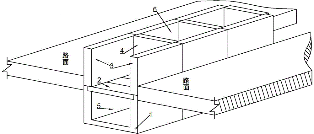
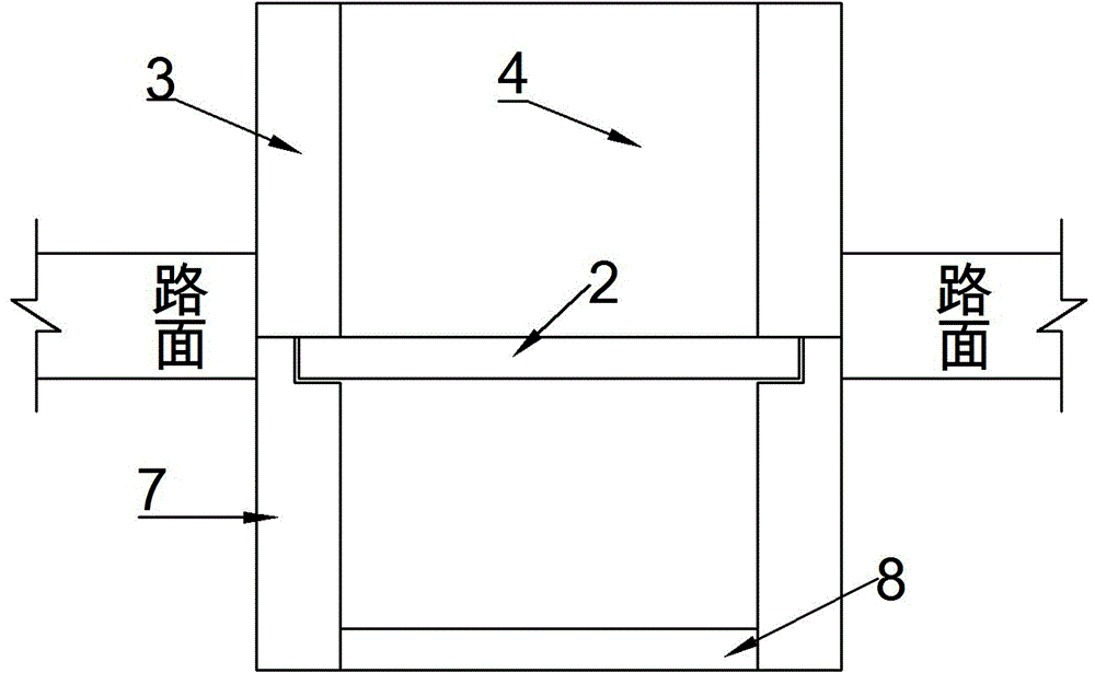
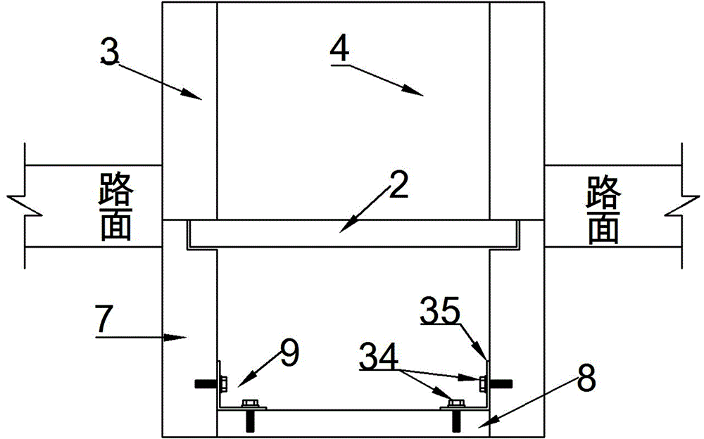
[0068] Such as figure 1 A variable emergency isolation belt is shown, including a U-shaped base trough 1, a movable cover 2, a lateral baffle 3 and a transverse baffle 4, and the feature is that the movable cover 2 is located in the U-shaped base trough 1 The upper part, together with the U-shaped base groove 1, encloses a tunnel 5, and the at least two lateral baffles 3, at least two transverse baffles 4, and the movable cover 2 jointly enclose an empty groove 6. When a traffic accident occurs on the road and forms a blockage, the maintenance personnel can use simple lifting equipment to lift the lateral baffle 3, the transverse baffle 4 and the movable cover 2, and transfer the gravel 26 and / or soil 27 in the emp...


PUM


Abstract

The invention discloses a variable emergency isolation belt, which relates to the field of traffic and road engineering. The variable emergency isolation belt includes a U-shaped base groove (1), a movable cover (2), a lateral baffle (3) and a transverse baffle (4), and the feature is that the movable cover (2) It is located on the upper part of the U-shaped foundation groove (1), and together with the U-shaped foundation groove (1), forms a tunnel (5), the at least two lateral baffles (3), at least two transverse baffles (4) and The movable cover plate (2) jointly encloses an empty slot (6). It is mainly used for traffic accidents on roads, maintenance personnel can use simple hoisting equipment to lift the lateral baffle (3), horizontal baffle (4) and movable cover (2), quickly open the isolation belt, and relieve Traffic jam stress. The invention has excellent isolation and anti-collision performance, easy and quick lane change, low cost, and is also convenient to expand multiple functions such as solar energy, electronic monitoring, drainage and disaster reduction.

Description

technical field [0001] The invention belongs to the field of traffic and road engineering, in particular to a variable emergency isolation belt for roads. Background technique [0002] The isolation zone in the middle of the highway, especially the isolation zone in the middle of the expressway, as a necessary facility for high-grade highways, plays a very important role in driving safety, driving comfort, road landscaping, anti-glare facilities and communication pipeline configuration. important role. People often compare the isolation zone in the middle of the expressway to the "lifeline" set up to maintain the safety of two-way vehicles. However, with the high-speed take-off of my country's economy, the number of vehicles on the road is increasing day by day, and the speed of driving is increasing day by day, but the technical level of this central isolation zone as a life protection line has not been able to increase day by day and keep pace with the times. The outstand...

Claims


Application Information

Patent Timeline
Patent Type & Authority Patents(China)
IPC IPC(8): E01F15/12
Inventor 傅礼铭陈颖环傅纤鹤
Owner 傅礼铭
Why Eureka
Try Eureka