Transitional junction from concrete-filled steel tube combination column to reinforced concrete column

A technology for reinforced concrete columns and concrete-filled steel tubes, which is applied in the field of nodes transitioning from concrete-filled steel tubular composite columns to concrete columns, can solve the problems of difficulty in bundling and positioning of steel bars, sudden changes in stiffness and bearing capacity, and poor concrete pouring and tamping, so as to meet the requirements of earthquake resistance Performance requirements, avoiding sudden changes in stiffness and bearing capacity, and the effect of simplifying construction procedures

Active Publication Date: 2014-02-26
香港华艺设计顾问(深圳)有限公司
View PDF6 Cites 10 Cited by
  • Summary
  • Abstract
  • Description
  • Claims
  • Application Information

AI Technical Summary

Problems solved by technology

If the steel pipe in the column rises to a certain floor, after the bearing capacity check, the concrete column with the same cross-section as the concrete-filled steel pipe composite column of this floor can also meet the vertical bearing capacity requirements, if the steel pipe is only cut off at the floor position, the cross-sectional form of the column will be transformed directly If it is a concrete column, there may be a sudden change in the stiffness and bearing capacity of the floor, which may form a weak floor, which is not conducive to the earthquake resistance of the building
The existing commonly used transition nodes have the disadvantages of difficult binding and positioning of steel bars and poor concrete pouring and tamping to varying degrees.

Method used


Image

  • Transitional junction from concrete-filled steel tube combination column to reinforced concrete column
  • Transitional junction from concrete-filled steel tube combination column to reinforced concrete column
  • Transitional junction from concrete-filled steel tube combination column to reinforced concrete column

Examples


Embodiment Construction

[0024] The specific implementation manners of the present invention will be further described in detail below in conjunction with the accompanying drawings.

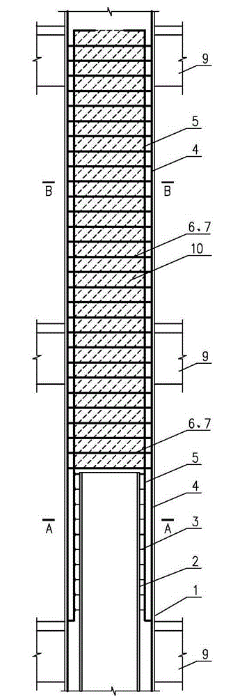
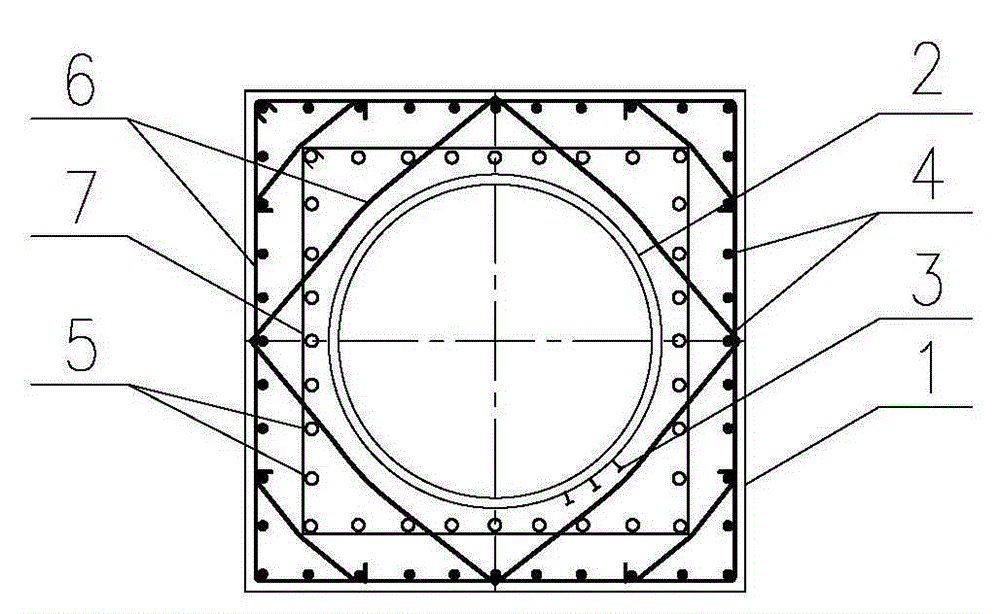
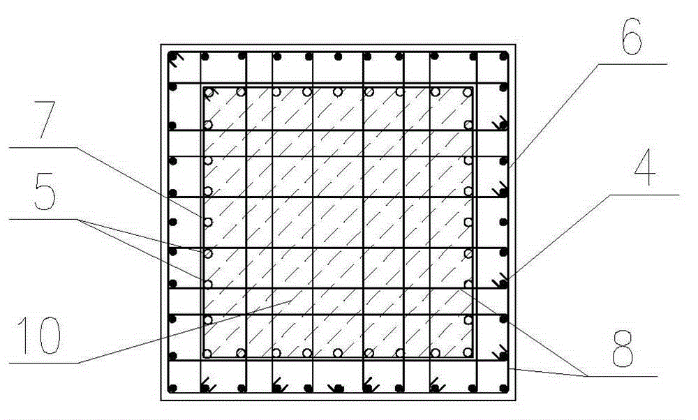
[0025] The details of the column body of a steel pipe concrete composite column to a reinforced concrete column transition node used in high-rise and super high-rise buildings according to the present invention are as follows figure 1 shown. Among them, the cross section of the steel pipe concrete composite column is rectangular, and the steel pipe 2 is arranged in the concrete column 1, and the cross section of the steel pipe 2 is circular. Afterwards, the steel pipe 2 extends upwards from the floor to the middle of the floor and is cut off. The steel pipe 2 is no longer installed on the upper floors. The steel pipe 2 is set in the center of the concrete column 1. The minimum distance is 200mm. Set the core column longitudinal reinforcement 5 and the core column stirrup 7 on the transitional floor, and extend upward ...


PUM


Abstract

The invention discloses a transitional junction from a concrete-filled steel tube combination column to a reinforced concrete column. The column section at the transitional layer where the transitional junction locates comprises the concrete column, a steel tube, external longitudinal bars, external stirrups, core longitudinal bars and core stirrups. The concrete-filled steel tube combination column is formed by arranging the steel tube in the middle of the concrete column. The section of the concrete-filled steel tube combination column is rectangular, and the section of the steel tube is circular. The external longitudinal bars and the external stirrups are arranged in the concrete column outside the steel tube, and the inside and the outside of the steel tube are poured with concrete simultaneously. The transitional layer of weakness is avoided, feasibility and convenience in construction are taken into consideration sufficiently, and a novel junction form with the advantages of direct transmission and construction easiness is provided for transition from the concrete-filled steel tube combination column to the reinforced concrete column. In addition, the transitional junction is applicable to high-rise and ultra-high-rise buildings and has broad application range and space.

Description

technical field [0001] The invention relates to a transition node for frame columns of different cross-section forms in high-rise and super high-rise buildings, in particular to a node for the transition from a steel tube concrete composite column to a concrete column, which belongs to an innovative technology for transition nodes of frame columns of high-rise and super high-rise buildings . Background technique [0002] At present, there are many options for the cross-section selection of frame columns in high-rise and super high-rise buildings. As a new type of column cross-section form, steel-filled steel-filled composite columns have been widely used in practical engineering in recent years. When the floor extends upward to a certain floor height, considering the economy and feasibility, the column section form can be changed to a reinforced concrete column without increasing the column section size. Reasonable transitional joints for composite columns to reinforced con...

Claims


Application Information

Patent Timeline
Patent Type & Authority Applications(China)
IPC IPC(8): E04B1/58
Inventor 张伟王兴法黄俊海刘俊
Owner 香港华艺设计顾问(深圳)有限公司
Why Eureka
Try Eureka