Steam-water separation type fuel-gas vertical straight-flow steam boiler

A steam-water separation and steam boiler technology, applied in the field of boilers, can solve the problems of poor steam-water separation effect of boilers, lower boiler efficiency, high steam humidity, etc., achieve the effect of strengthening steam-water separation effect, reducing manufacturing difficulty, and improving boiler efficiency

Inactive Publication Date: 2015-03-04
TAIJUNE BOILER IND KUSN
View PDF6 Cites 0 Cited by
  • Summary
  • Abstract
  • Description
  • Claims
  • Application Information

AI Technical Summary

Problems solved by technology

[0007] 1. Due to the structure of the boiler, sufficient steam-water separation equipment cannot be arranged in the upper annular header of this type of boiler. At the same time, this type of boiler requires a compact layout, and the secondary separation device cannot be arranged in a large and complicated manner, resulting in the steam-water separation of this type of boiler. The separation effect is not good, and the steam humidity is higher than that of other steam boilers with sufficient steam-water separation equipment;
[0008] 2. The hydrophobic device in the external steam-water separation device directly drains high-temperature water without effective use, which reduces the efficiency of the boiler

Method used


Image

  • Steam-water separation type fuel-gas vertical straight-flow steam boiler
  • Steam-water separation type fuel-gas vertical straight-flow steam boiler
  • Steam-water separation type fuel-gas vertical straight-flow steam boiler

Examples


Embodiment

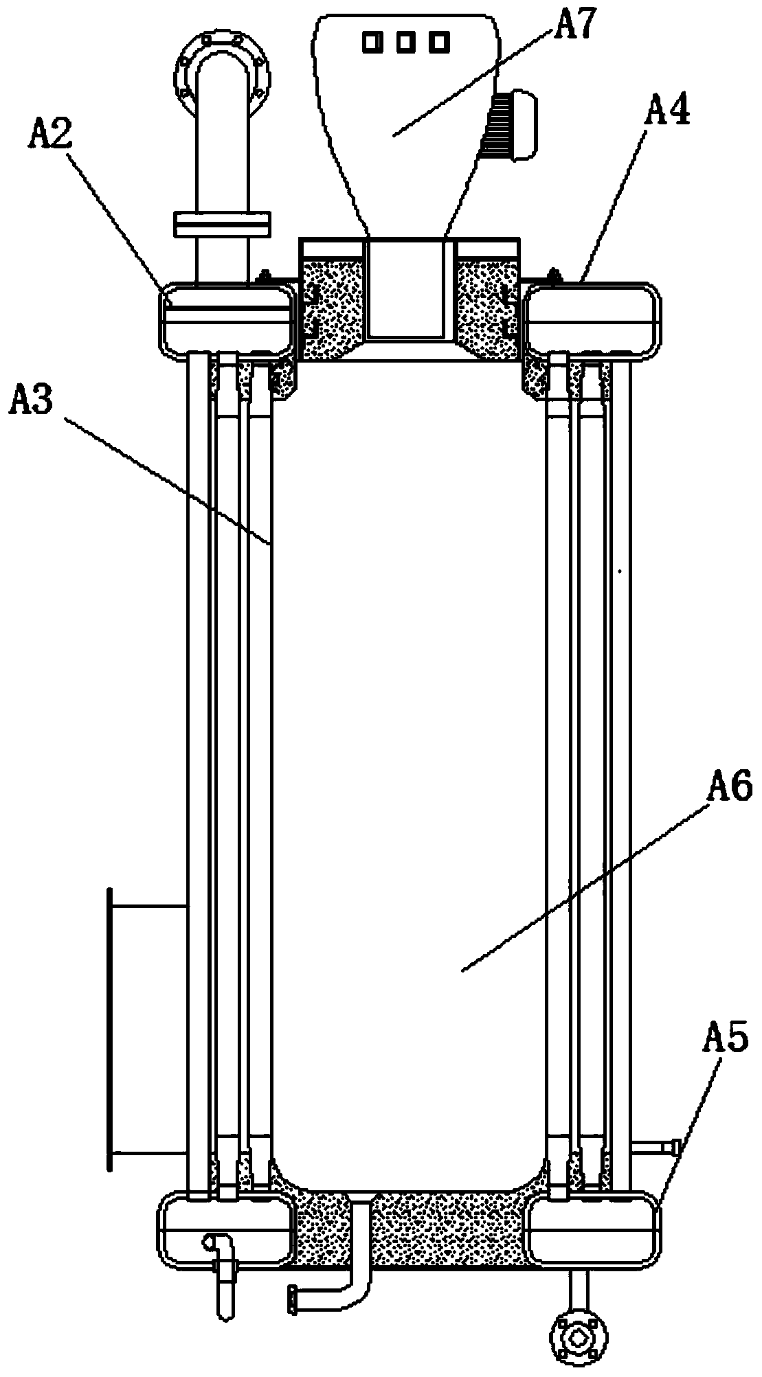
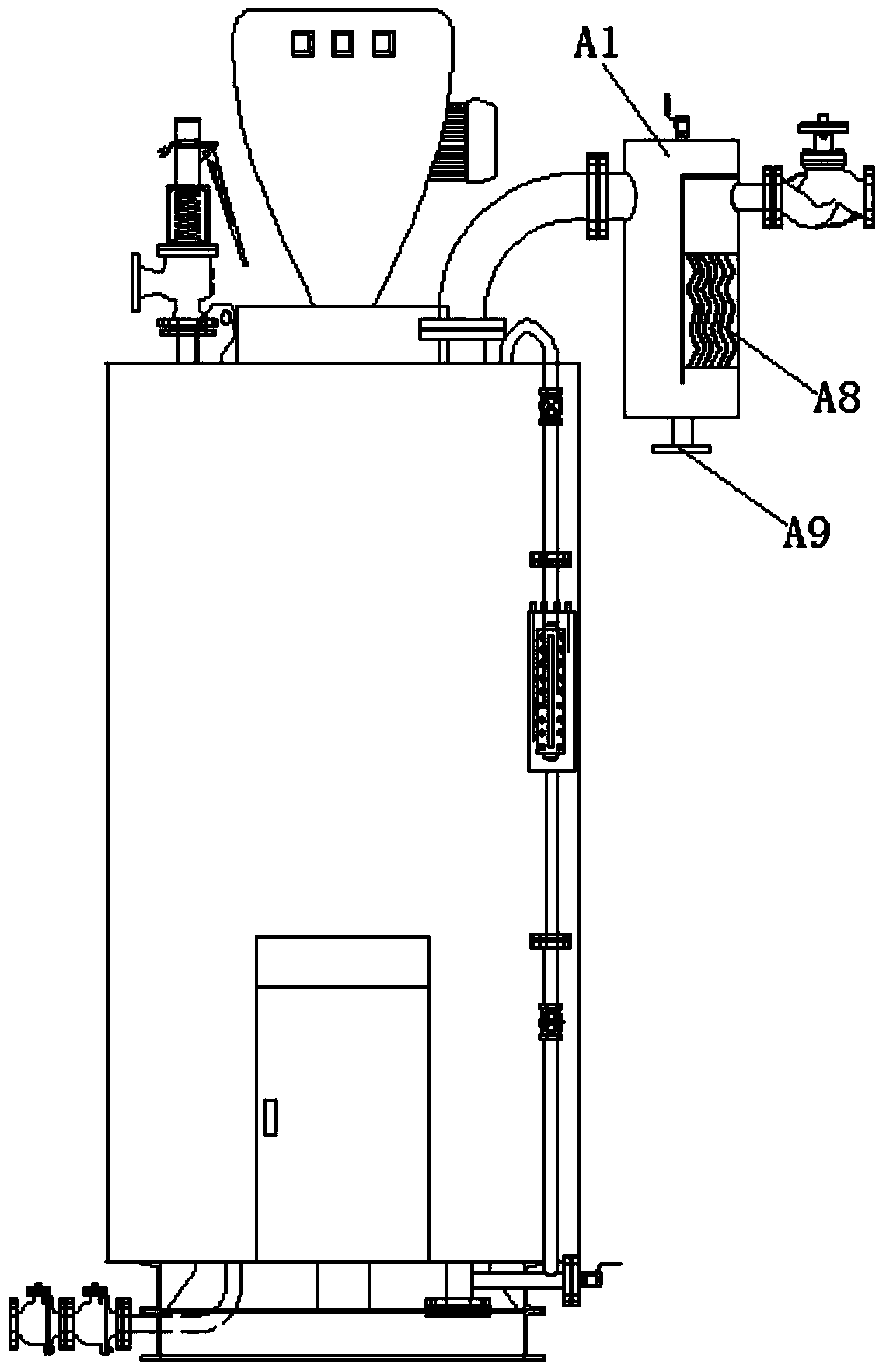
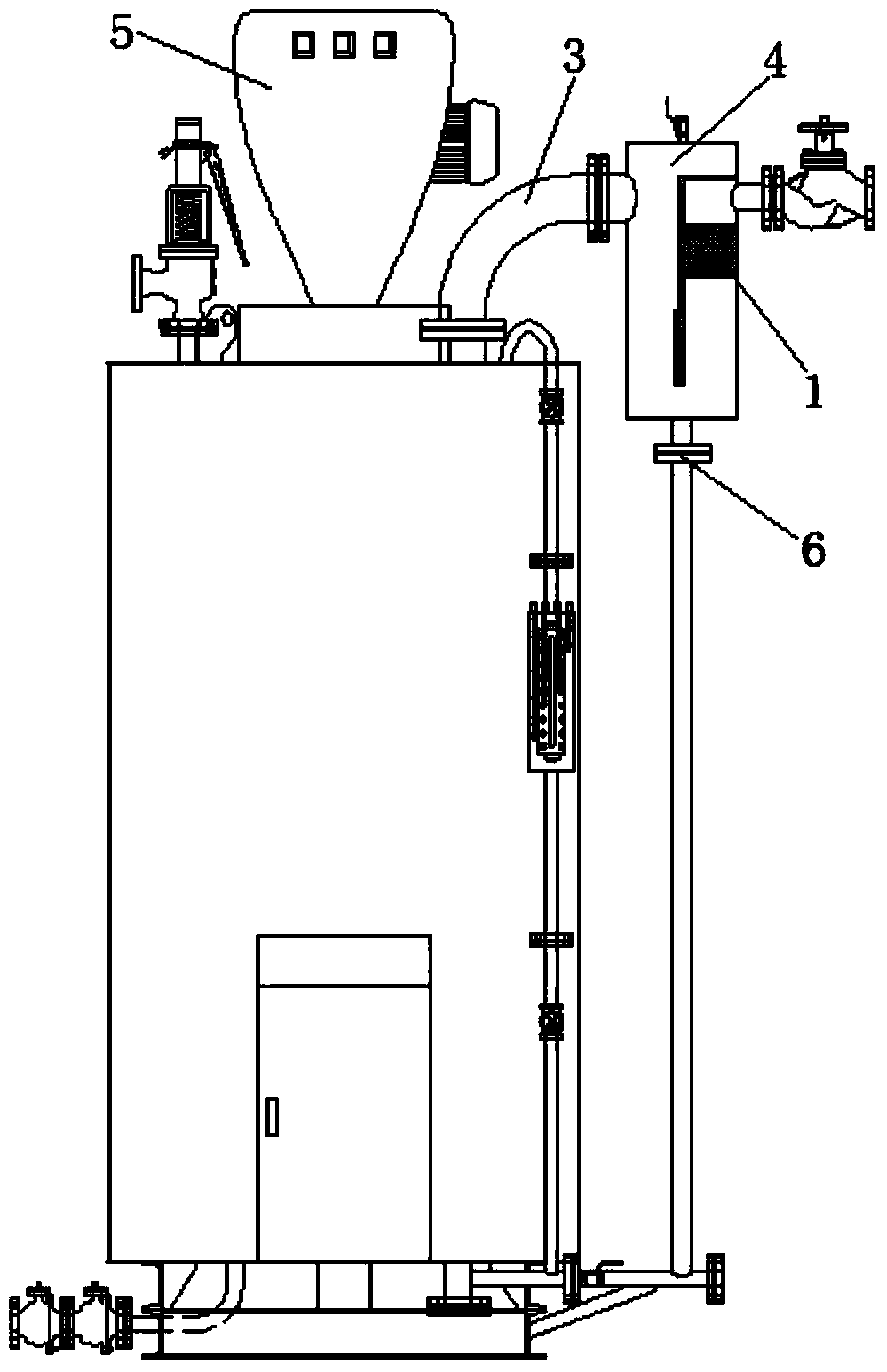
[0033] Example: A steam-water separation type oil and gas vertical tubular steam boiler, such as image 3 As shown, it includes a heating surface tube, an upper annular header 2, a lower annular header, a secondary steam-water separation header 4 and a burner 5. The heating surface tube communicates with the upper annular header 2 and the lower annular header. A combustion chamber is formed between the heating surface tube, the upper annular header 2 and the lower annular header, the burner 5 is arranged above the combustion chamber, and the upper annular header 2 is connected to the secondary through a steam connection pipe 3 The steam-water separation header 4 is in communication, and the secondary steam-water separation header 4 has a steam channel in which a stainless steel wire ball 1 is provided. In the secondary steam-water separation, the traditional corrugated plate in the secondary steam-water separation header is replaced with stainless steel wire balls, which reduces...


PUM


Abstract

The invention discloses a steam-water separation type fuel-gas vertical straight-flow steam boiler. The steam-water separation type fuel-gas vertical straight-flow steam boiler comprises a heated surface pipe, an upper-part ring-shaped container, a lower-part ring-shaped container, a secondary steam-water separation container and a burner, wherein the upper-part ring-shaped container is communicated with the secondary steam-water separation container by a steam connecting pipe; the secondary steam-water separation container is internally provided with a steam channel which is provided with a stainless steel wire ball. The steam-water separation type fuel-gas vertical straight-flow steam boiler disclosed by the invention has the advantages that a second porous plate is formed by perforating the traditional primary steam-water separation baffle, and two side sealing plates are additionally welded, so that the traditional simple separation method is changed, the steam flow flows into the second porous plate and further the primary separation efficiency is improved; in secondary steam-water separation, a corrugated plate in the traditional secondary steam-water separation container is replaced with the stainless steel ball, so that the manufacturing difficulty is reduced; the lower part of the secondary steam-water separation container is provided with a steam-water separation water-return device, so that high-temperature water separated from the secondary steam-water separation container enters the boiler again, and further the energy-saving requirement is met.

Description

[0001] This application is a divisional application of invention patent application number: 201110199126.2. The original application date: 2011-07-15. The name of the invention is a steam-water separation type fuel gas vertical tubular steam boiler. Technical field [0002] The invention belongs to the field of boilers, and mainly relates to a vertical oil-fired and gas-fired tubular steam boiler with an improved steam-water separation structure. Background technique [0003] Boiler is a kind of heating equipment. It uses coal, oil and gas, biomass, etc. as fuel, and produces steam, hot water or other heat media from the heat generated by combustion to meet various needs in social production. Coal combustion The generated flue gas will seriously pollute the environment and endanger human health, and the combustion technology and flue gas treatment are more complicated; the calorific value of biomass fuel is too low, and the boiler layout takes up a large space; oil and gas boilers ...

Claims


Application Information

Patent Timeline
Patent Type & Authority Patents(China)
IPC IPC(8): F22B31/08
Inventor 董毓梅顾大弟谢理明盛天瑜吴行跃赵建峰李全利王瑞霞
Owner TAIJUNE BOILER IND KUSN
Why Eureka
Try Eureka