Single-layer capacitive two-dimensional touch sensor with mutually crossed adjacent electrodes

A touch sensor, adjacent electrode technology, applied in the direction of instrument, electrical digital data processing, input/output process of data processing, etc., can solve the problems of limited contact area, poor linearity, inability to implement mobile phones, etc., to overcome the contact area Limited, improved linearity effect

Inactive Publication Date: 2014-02-26
SHENZHEN GOODIX TECH CO LTD
View PDF5 Cites 6 Cited by
  • Summary
  • Abstract
  • Description
  • Claims
  • Application Information

AI Technical Summary

Problems solved by technology

[0002] Touch screen technology is more and more widely used. For touch screens that support passive pens, due to the limited contact area between the passive pen and the touch screen, when the electrode size (pitch) is large (such as greater than or equal to 4mm), the data of the

Method used


Image

  • Single-layer capacitive two-dimensional touch sensor with mutually crossed adjacent electrodes
  • Single-layer capacitive two-dimensional touch sensor with mutually crossed adjacent electrodes
  • Single-layer capacitive two-dimensional touch sensor with mutually crossed adjacent electrodes

Examples


Embodiment 1

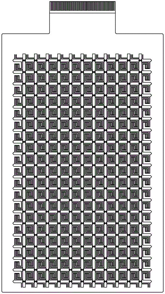
[0034] Figure 1A The schematic diagram of the overall wiring of the two-dimensional touch sensor provided for the first embodiment, due to the dense wiring, is especially enlarged by selecting the shape of some sensing electrodes and driving electrode blocks, specifically as follows Figure 1B to Figure 1D shown in detail below.

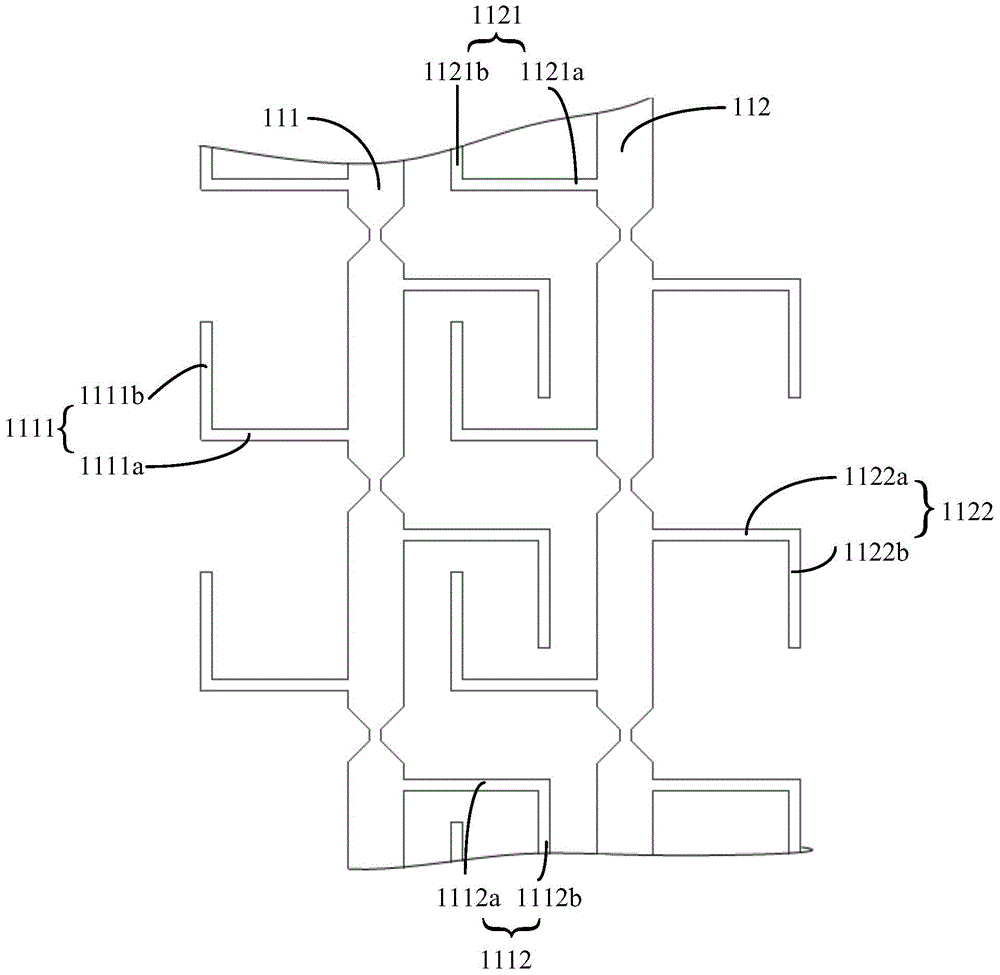
[0035] refer to Figure 1B , each sensing electrode includes the sensing electrode body, Figure 1B The adjacent sensing electrode bodies 111 and 112 are shown. The sensing electrode body has several extensions bent at least once on both sides respectively, and among the several extensions bent at least once on each side, the latter The bending parts are all bent at the ends of the previous bending part in a direction perpendicular to the previous bending part, and the directions of the most end bending parts on both sides are opposite. Figure 1BTwo bending parts are taken as an example in the figure. The sensing electrode body 111 has an extensi...

Embodiment 2

[0041] The design of embodiment two is similar to embodiment one, by Figure 2A with Figure 2B It can be seen that the difference is that in the second embodiment, the sensing electrode and the driving electrode block have one more bending part than in the first embodiment, and in the first embodiment, the sensing electrode has two bending parts, and the driving electrode block has three bending parts. , while in the second embodiment, there are three and four respectively. In addition, the direction of bending is also opposite. No more details.

Embodiment 3

[0043] refer to Figure 3A , each sensing electrode includes a sensing electrode body, the sensing electrode body has an extension to its two sides, the extensions of two adjacent sensing electrodes cross each other but do not touch each other, such as the left side of the sensing electrode body 311 has several extensions The portion 3111 has several extensions 3112 to the right, and the sensing electrode body 312 has several extensions 3121 to the left and several extensions 3122 to the right. The extensions 3112 and 3121 cross each other but do not touch each other.

[0044] refer to Figure 3B , each driving electrode block includes a driving electrode block body, and the driving electrode block bodies 321 and 322 respectively have extensions that are bent twice from the two ends as starting points to both sides, such as the left end point of the driving electrode block body 321 facing down and then Bending to the right, the right end point of the driving electrode block ...


PUM


Abstract

The invention is applicable to the field of touch technologies, and provides a single-layer capacitive two-dimensional touch sensor with mutually crossed adjacent electrodes. The single-layer capacitive two-dimensional touch sensor comprises a substrate. Inductive electrode patterns and driving electrode patterns are arranged on the substrate, the inductive electrode patterns comprise a plurality of inductive electrodes, the driving electrode patterns comprise a plurality of driving channels, and each driving channel comprises a plurality of driving electrode blocks which are connected with one another; the inductive electrodes and/or the driving electrode blocks are provided with extension portions, mutually cross and non-contact structures are formed among the adjacent inductive electrodes, among the adjacent driving electrodes and/or among the inductive electrodes and the adjacent driving electrode blocks via the extension portions. The single-layer capacitive two-dimensional touch sensor has the advantages that the 'mutually crossed' structures are formed among the adjacent electrodes, so that influence of a driven stylus on the adjacent driving channels/adjacent inductive channels is improved, the problem of the limited contact surface of an existing driven stylus can be solved to a certain extent, and the linearity can be improved.

Description

technical field [0001] The invention belongs to the technical field of touch control, and in particular relates to a single-layer capacitive two-dimensional touch sensor in which adjacent electrodes cross each other. Background technique [0002] Touch screen technology is more and more widely used. For touch screens that support passive pens, due to the limited contact area between the passive pen and the touch screen, when the electrode size (pitch) is large (such as greater than or equal to 4mm), the data of the adjacent channel by the passive pen The impact is too small, resulting in poor linearity. To solve this problem, the general method is to reduce the pitch, such as 3.5mm, but it will increase the number of channels, which cannot be implemented for mobile phones with narrow bezels. Contents of the invention [0003] The technical problem to be solved by the present invention is to provide a single-layer capacitive two-dimensional touch sensor in which adjacent el...

Claims


Application Information

Patent Timeline
IPC IPC(8): G06F3/044
CPCG06F3/0443G06F3/0446G06F2203/04111
Inventor 刘武凌伟赵凤林宏寿李海张平
Owner SHENZHEN GOODIX TECH CO LTD
Why Eureka
Try Eureka