Splicing display apparatus control system

A splicing display and device control technology, applied to static indicators, instruments, etc., can solve problems such as messy wiring of splicing display devices, achieve the effects of saving wires, reducing construction difficulty, and avoiding messy wiring

Inactive Publication Date: 2014-02-26
GUANGDONG VTRON TECH CO LTD
View PDF11 Cites 3 Cited by
  • Summary
  • Abstract
  • Description
  • Claims
  • Application Information

AI Technical Summary

Problems solved by technology

[0004] Based on this, it is necessary to provide a splicing display device control system for the deficiencies of the existing technology, which uses the power line as a communication carrier instead of the traditional network cable and twisted pair, saves a lot of wires, avoids the problem of messy wiring behind the splicing display device, and can Reduce construction difficulty and equipment costs, protect the existing laying network to the greatest extent, and have intelligent scene lighting control function, adjust the background light according to the scene set by the user

Method used


Image

  • Splicing display apparatus control system
  • Splicing display apparatus control system
  • Splicing display apparatus control system

Examples


Embodiment Construction

[0013] In order to further understand the features, technical means, and specific objectives and functions achieved by the present invention, the present invention will be further described in detail below in conjunction with the accompanying drawings and specific embodiments.

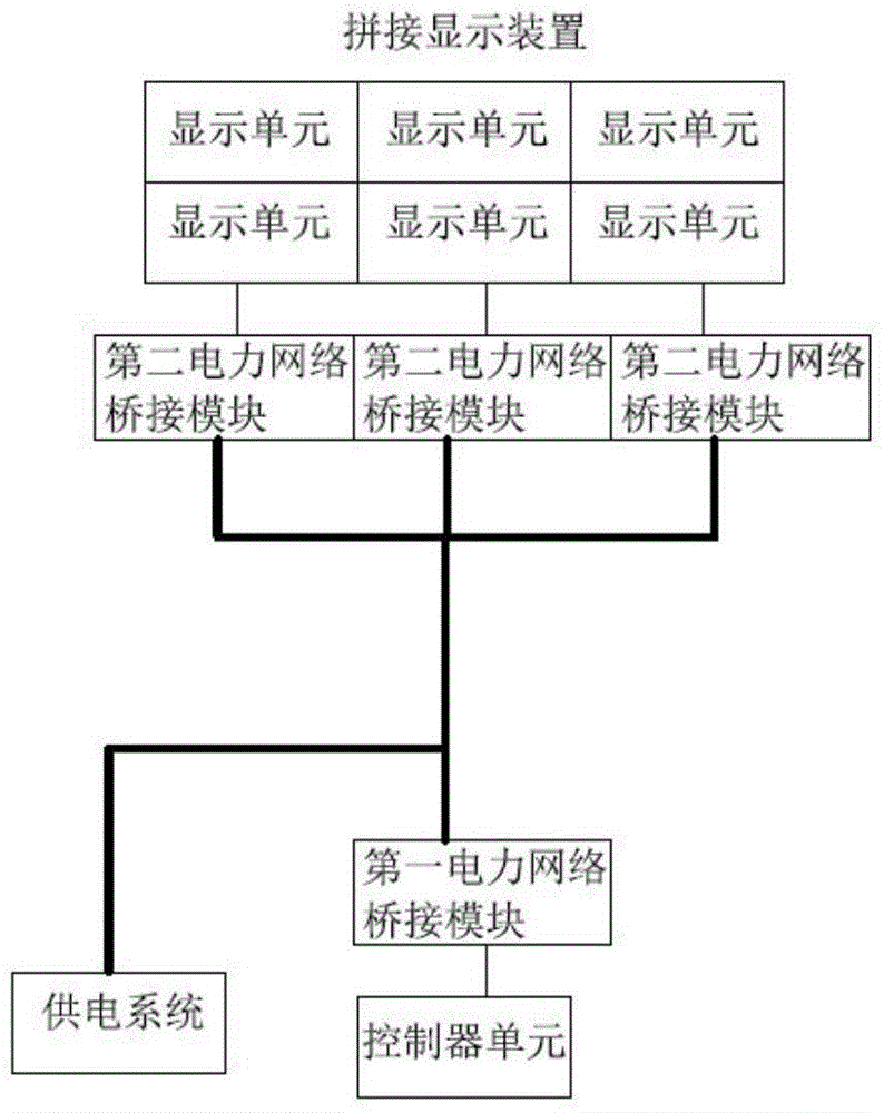
[0014] Such as figure 1 As shown, the splicing display device control system of the present invention includes a controller unit, a first power network bridging module, and a second power network bridging module respectively connected to the display unit of the splicing display device; the controller unit passes through the first power network bridging module connected to the power line, the power line is connected to the power supply system, the display unit is connected to the power line through the second power network bridge module; the controller unit outputs a control signal to the A first power network bridging module, the first power network bridging module loads the control signal onto the pow...


PUM


Abstract

The invention discloses a splicing display apparatus control system. The system comprises a controller unit, a first electric power network bridging module, and second electric power network bridging modules respectively connected with the display units of a splicing display apparatus, wherein the controller unit is connected with a power line through the first electric power network bridging module; the display units are connected with the power line through the second electric power network bridging modules; the controller unit outputs a control signal to the first electric power network bridging module according to control operation, and the first electric power network bridging module loads the control signal to the power line; and the second electric power network bridging modules obtain the control signal from the power line and sends the control signal to corresponding display units. According to the invention, the display units are connected with the power line through the first electric power network bridging module so as to be connected to an electric power network so that a large quantity of wire rods is saved, there are links for mutual communication among the forgoing parts, and intelligent brightness adjustment can be realized according to the background light mode determined by the controller unit.

Description

technical field [0001] The present invention relates to the technical field of splicing display, in particular to a control system of a splicing display device. Background technique [0002] The traditional splicing display device control system is based on LAN and RS485 industrial network. Each display unit of the splicing display device has a serial interface or network cable interface and at least one video input port such as DVI interface. The serial interface communicates and controls the display unit, and the processor connects to the video input port through the video cable to transmit the content of the image signal generated by the corresponding display unit. [0003] Peripheral devices such as dimming lights are far away from the control computer, and the control computer generally needs to convert serial port signals into RS485 differential signals for transmission to peripheral devices. Therefore, in addition to power lines for connection, this splicing display ...

Claims


Application Information

Patent Timeline
Patent Type & Authority Applications(China)
IPC IPC(8): G09G3/20
Inventor 伍健庭
Owner GUANGDONG VTRON TECH CO LTD
Why Eureka
Try Eureka