Photovoltaic assembly junction box with electrical connection protection
A photovoltaic module and electrical connection technology, applied in the direction of electrical components, photovoltaic power generation, photovoltaic modules, etc., can solve the problems of insufficient electrical connection protection and poor waterproof protection ability of junction boxes, so as to ensure safe and effective operation, avoid messy wiring, Guarantees the effect of sealing performance
- Summary
- Abstract
- Description
- Claims
- Application Information
AI Technical Summary
Problems solved by technology
Method used
Image
Examples
Embodiment 1
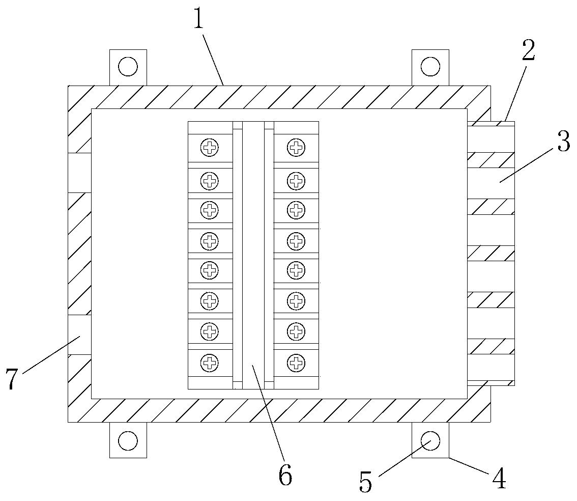
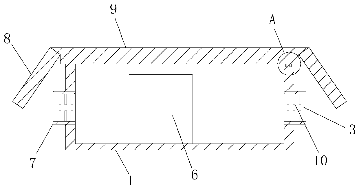
[0030] Example 1, please refer to Figure 1~2 , a photovoltaic module junction box with electrical connection protection, including a box body 1, a terminal row 6 is arranged inside the box body 1, an outlet 7 is opened on the left side of the box body 1, and an outlet 7 is opened on the left side of the box body 1. The right side is provided with an incoming line sleeve 2, and an incoming line slot 3 is opened in the incoming line sleeve 2, and the upper and lower sides of the box body 1 are connected with a fixed piece 4, and the fixed piece 4 is provided with a screw hole 5, so The box body 1 is provided with a box cover 9, and the left and right ends of the box cover 9 are respectively connected with sloping plates 8, and the sloping plates 8 are made of thin steel sheets. The upper and lower positions in the mouth 7 are respectively provided with rubber strips 10, and the rubber strips 10 are made of chloroether rubber, chlorosulfonated polyethylene rubber, fluorine rubbe...
Embodiment 2
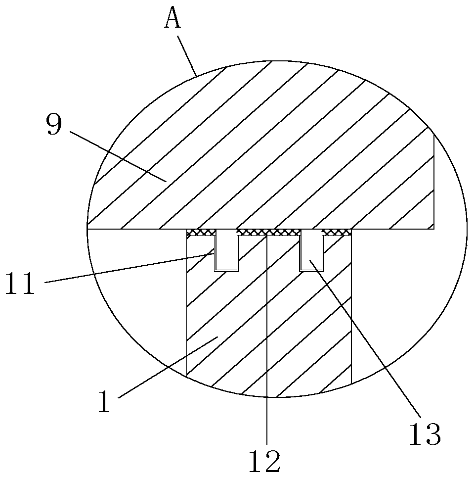
[0031] Example 2, please refer to Figure 1~3 , a photovoltaic module junction box with electrical connection protection, including a box body 1, a terminal row 6 is arranged inside the box body 1, an outlet 7 is opened on the left side of the box body 1, and an outlet 7 is opened on the left side of the box body 1. The right side is provided with an incoming line sleeve 2, and an incoming line slot 3 is opened in the incoming line sleeve 2, and the upper and lower sides of the box body 1 are connected with a fixed piece 4, and the fixed piece 4 is provided with a screw hole 5, so The box body 1 is provided with a box cover 9, and the left and right ends of the box cover 9 are respectively connected with sloping plates 8, and the sloping plates 8 are made of thin steel sheets. The upper and lower positions in the mouth 7 are respectively provided with rubber strips 10, and the rubber strips 10 are made of chloroether rubber, chlorosulfonated polyethylene rubber, fluorine rubbe...
Embodiment 3
[0033] Embodiment three, please refer to Figure 1~2And 4, a photovoltaic module junction box with electrical connection protection, including a box body 1, a wiring terminal row 6 is arranged in the box body 1, an outlet 7 is opened on the left side of the box body 1, and the box body 1 is provided with an inlet sleeve 2 on the upper right side, and an inlet slot 3 is opened inside the wire inlet sleeve 2. The upper and lower sides of the box body 1 are connected with a fixing piece 4, and the fixing piece 4 is provided with a screw hole 5 , the box body 1 is provided with a box cover 9, and the left and right ends of the box cover 9 are respectively connected with sloping plates 8, and the sloping plates 8 are made of thin steel sheets. The upper and lower positions in the outlet port 7 are respectively provided with rubber strips 10, and the rubber strips 10 are made of chloroether rubber, chlorosulfonated polyethylene rubber, fluorine rubber, butyl rubber and neoprene rubb...
PUM
 Abstract
Description
Claims
Application Information
 - R&D
- Intellectual Property
- Life Sciences
- Materials
- Tech Scout
- Unparalleled Data Quality
- Higher Quality Content
- 60% Fewer Hallucinations
Browse by: Latest US Patents, China's latest patents, Technical Efficacy Thesaurus, Application Domain, Technology Topic, Popular Technical Reports.
© 2025 PatSnap. All rights reserved.Legal|Privacy policy|Modern Slavery Act Transparency Statement|Sitemap|About US| Contact US: help@patsnap.com


