Fuse wire and fuse tube for fuse

A fuse and fuse technology, applied in the direction of electrical components, circuits, emergency protection devices, etc., can solve the problems of low safety protection factor, line burnout, easy to bend, etc., and achieve the effect of improving safety protection factor

Active Publication Date: 2014-02-26
BEIJING DINGYI TONGYUAN SCI & TECH DEV CO LTD
View PDF5 Cites 0 Cited by
  • Summary
  • Abstract
  • Description
  • Claims
  • Application Information

AI Technical Summary

Problems solved by technology

[0004] The existing fuses and fuse tubes of fuses have the following technical defects: 1) Generally, the fuses are relatively short, and are connected by a single fuse, and the disconnection point is on the upper side. It is difficult to pull out the fuse when it is disconnected. , the melt is pulled out due to heat deformation, if the tension of the spring is weakened, the pop-up speed will slow down after the fuse is blown, so that it cannot be pulled out quickly in case of a fault, and the continuous intermittent discharge generated at this time will damage the equipment; 2) the current fuse (Except for the melt) are all connected by copper stranded wires. This kind of fuse must be tightened with a spring with a large deformation coefficient, otherwise it is easier to bend, which weakens the elasticity of the spring, and is even more dangerous. Burned; 3) Ordinary fuses have only one external arc extinguishing tube (melting tube), and the internal space is large, the arc generated is large, and the pressure of the gas in the large space is reduced, which makes the arc extinguishing and falling time longer, which is not conducive to protection circuit equipment
[0005] It can be seen that the fuses and fuse tubes in the prior art still have potential safety hazards of burning lines and damaging equipment, and the safety protection factor is not high, which needs further improvement

Method used


Image

  • Fuse wire and fuse tube for fuse
  • Fuse wire and fuse tube for fuse
  • Fuse wire and fuse tube for fuse

Examples


Embodiment Construction

[0020] The present invention will be described in detail below in conjunction with the implementations shown in the drawings, but it should be noted that these implementations are not limitations of the present invention, and those of ordinary skill in the art based on the functions, methods, or structural changes made by these implementations Equivalent transformations or substitutions all fall within the protection scope of the present invention.

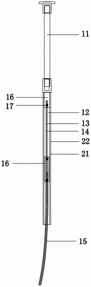
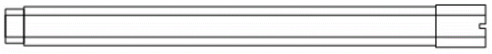
[0021] ginseng Figure 1 to Figure 3 as shown, figure 1 It is a schematic diagram of the combined structure of the fuse fuse and the fuse pipe fuse; figure 2 It is a structural schematic diagram of the fuse fuse of the present invention and the arc extinguishing tube in the inner layer of the fuse tube; image 3 It is a schematic diagram of the combined structure of the fuse, the outer layer arc extinguishing tube and the inner layer arc extinguishing tube of the fuse of the present invention.

[0022] In this embodiment, the ...


PUM

PropertyMeasurementUnit
Lengthaaaaaaaaaa
Diameteraaaaaaaaaa
Diameteraaaaaaaaaa

Abstract

The invention provides a fuse wire and a fuse tube for a fuse. The fuse wire comprises a copper-plated stainless steel rod (11), a first melt (12), a second melt (13), a stainless steel wire (14) and a zinc-plated copper stranded wire (15) which are connected through a connecting component (16). The fuse tube comprises an inner-layer arc extinction tube (21) and an outer-layer arc extinction tube (22), wherein the first melt (12), the second melt (13) and the stainless steel wire (14) are nested in the inner-layer arc extinction tube (21); the inner-layer arc extinction tube (21) is nested in the outer-layer arc extinction tube (22). According to the fuse wire and the fuse tube, adopting the structure, for the fuse, the safety protection coefficient of circuit equipment is increased.

Description

technical field [0001] The invention relates to the field of high and low voltage power distribution and control, in particular to a fuse, a fuse and a fuse. Background technique [0002] Fuse is a kind of overcurrent protector, mainly composed of melt, fuse tube and external filler. Fuse is a device that protects electronic and electrical equipment from current and overheating, and avoids serious damage caused by internal failures of electronic equipment. [0003] At the moment when the current is disconnected, due to the self-induced electromotive force in the circuit, an arc will be generated at the disconnection point. The larger the breaking current, the stronger the arc generated. If the arc is not extinguished in time, the current can still pass through the arc to form a loop. This also happens when a fuse is blown. Based on this, when designing a fuse, the arc extinguishing capability of the fuse is considered as a main technical indicator. [0004] The existing ...

Claims


Application Information

Patent Timeline
IPC IPC(8): H01H85/08H01H85/175H01H85/38
Inventor 唐国初孙超
Owner BEIJING DINGYI TONGYUAN SCI & TECH DEV CO LTD
Why Eureka
Try Eureka