
High-speed needle insertion apparatus

A pin insertion device and high-speed technology, applied in the field of automation, can solve problems such as slow pin insertion speed, unequal number of PINs, and low productivity, and achieve the effects of improving production efficiency, improving production efficiency, and reducing equipment noise

Active Publication Date: 2014-02-26
KUNSHAN INNO STAR AUTOMATION TECH
View PDF6 Cites 4 Cited by
  • Summary
  • Abstract
  • Description
  • Claims
  • Application Information

AI Technical Summary

Problems solved by technology

[0003] At present, one of the traditional pin insertion methods is to use manual row insertion for single-piece pin insertion, and the pin insertion speed is slow. The other is to use a cylinder mechanism for pin insertion, and the pin insertion speed can only reach about SPM150. There are many types, and the number of PINs is not equal, the batch is large, and the cylinder pin insertion mechanism cannot meet the actual needs. In addition, the cylinder pin insertion mechanism has high requirements on the incoming material size and specifications. In actual use, there are many failures and difficult maintenance and adjustment, resulting in Low productivity, causing problems for production and manufacturing

Method used


Image

  • High-speed needle insertion apparatus
  • High-speed needle insertion apparatus
  • High-speed needle insertion apparatus

Examples


Embodiment Construction

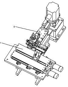
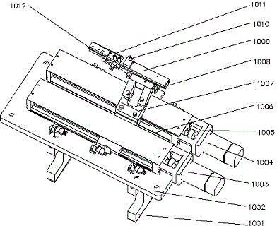
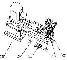
[0035] Such as figure 1 and figure 2 As shown, the present invention includes a product feeding mechanism 1 and a cam feeding pin mechanism 2. The feeding bracket 1001 is fixedly connected to the first feeding motor 1003 and the second feeding motor 1004 through the first connecting plate 1002, and the first feeding horse 1003 is connected to the first feeding motor 1004. The KK module 1005 is fixedly connected, the second feeding motor 1004 is fixedly connected with the second KK module 1006, the second KK module 1006 is fixedly connected with the second finger 1012 through the finger connector 1007, and the product track 1009 is located at the first finger The top of the claw 1008 is fixedly connected with the product pressing block 1011 through the positioning cover plate 1010 .

[0036] The product feeding mechanism 1 uses two sets of feeding structures. When one set is already working, the other set can return to the next product and follow the first set of mechanisms. ...


PUM


Abstract

The invention discloses a high-speed needle insertion apparatus. The apparatus comprises a product feeding mechanism and a cam feeding needle insertion mechanism. The product feeding mechanism comprises a feeding support, a first connection board, a first feeding motor, a second feeding motor, a first KK module, a second KK module, a poking claw connecting piece, a first poking claw, a second poking claw, a product track, a positioning cover plate and a product briquetting. The feeding support is fixedly connected with the first feeding motor and the second feeding motor through the first connection board. The first feeding motor is fixedly connected with the first KK module. The second feeding motor is fixedly connected with the second KK module. The second KK module is fixedly connected with the second poking claw through the poking claw connecting piece. The product track is located on a top of the first poking claw and is fixedly connected with the product briquetting through the positioning cover plate. The cam feeding needle insertion mechanism comprises a cam group assembly, a material belt feeding assembly, a material belt positioning assembly, a cutting-off and pressing-into assembly and a transmission power assembly. The mechanism of the apparatus of the invention is compact and production efficiency is high. The apparatus is especially suitable for complex needle insertion with high precision and small spacing.

Description

[0001] technical field [0002] The invention relates to the technical field of automation, in particular to a processing and assembling automatic pin-inserting device suitable for various connectors. Background technique [0003] At present, one of the traditional pin insertion methods is to use manual row insertion for single-piece pin insertion, and the pin insertion speed is slow. The other is to use a cylinder mechanism for pin insertion, and the pin insertion speed can only reach about SPM150. There are many types, and the number of PINs is not equal, the batch is large, and the cylinder pin insertion mechanism cannot meet the actual needs. In addition, the cylinder pin insertion mechanism has high requirements on the incoming material size and specifications. In actual use, there are many failures and difficult maintenance and adjustment, resulting in Low productivity has caused troubles to production and manufacturing. [0004] Therefore, a new technical solution is...

Claims


Application Information

Patent Timeline
Patent Type & Authority Applications(China)
IPC IPC(8): H01R43/00H01R43/20
Inventor 黄小芽
Owner KUNSHAN INNO STAR AUTOMATION TECH
Learn More