

Hanging brick special for kiln covers
A technology of kiln head and brick body, which is applied in the field of special hanging bricks for kiln head cover, which can solve the problems of inconvenient masonry and easy falling of fire cement, and achieve the effect of convenient masonry and improvement of masonry efficiency
- Summary
- Abstract
- Description
- Claims
- Application Information
AI Technical Summary
Problems solved by technology
Method used
Image

Examples
Embodiment 1
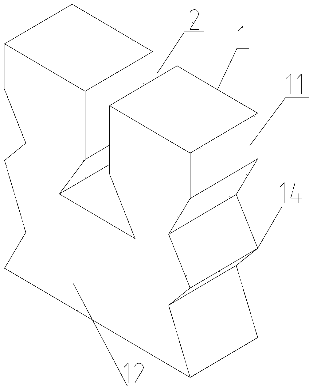
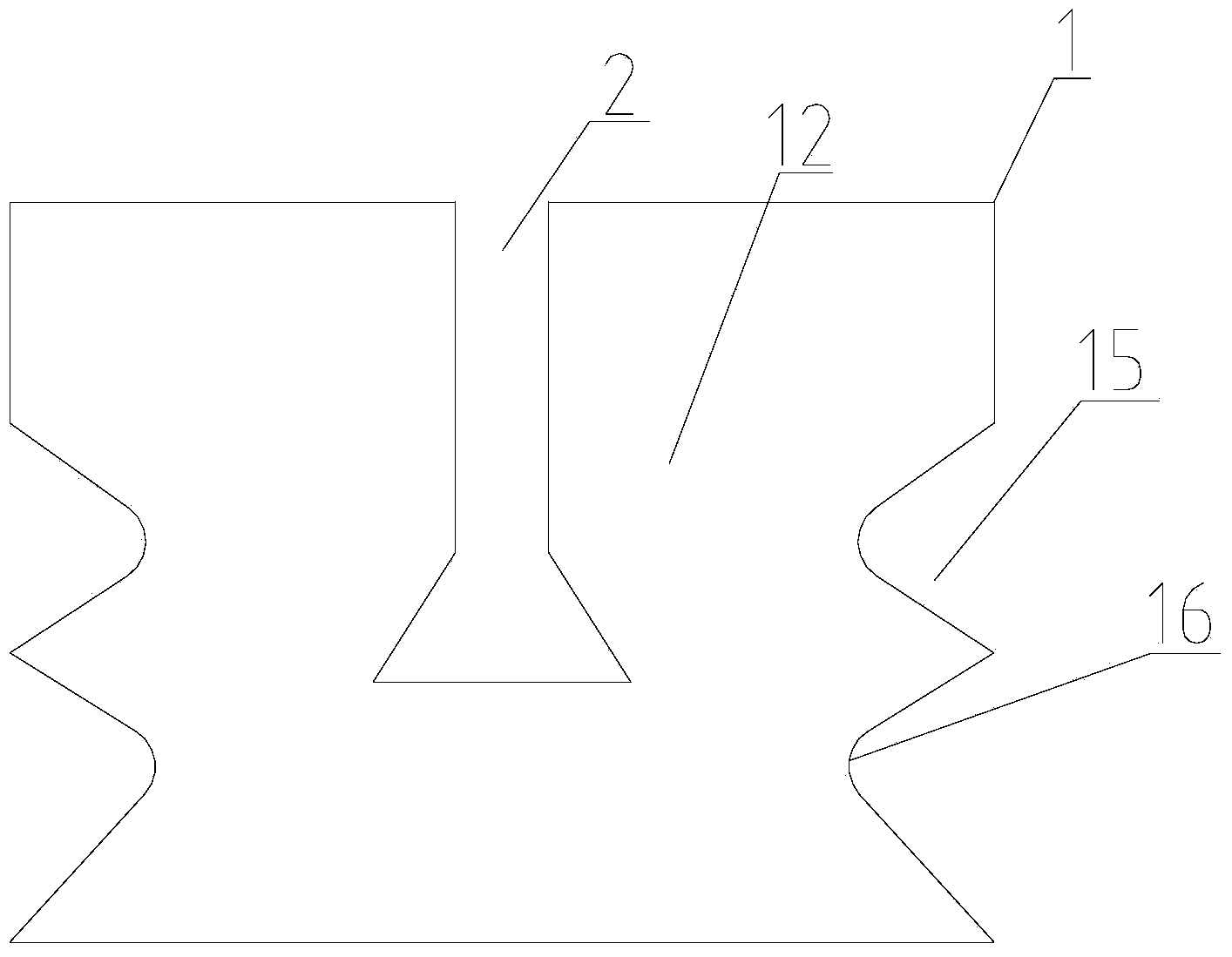
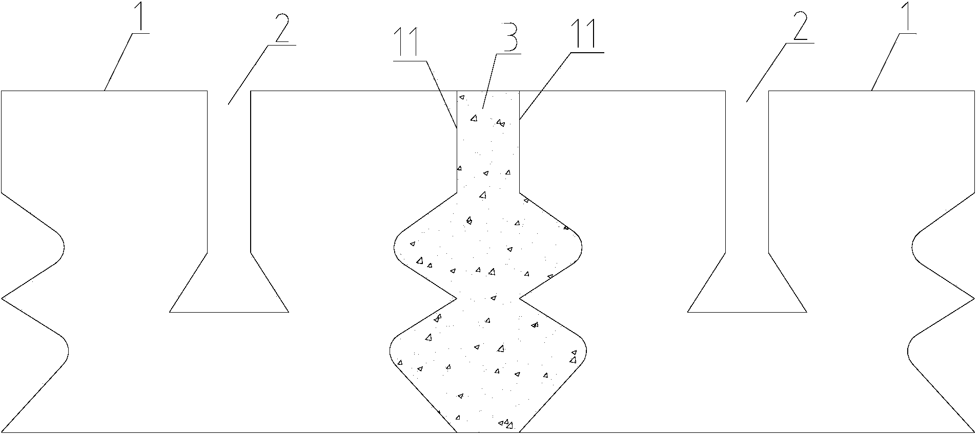
[0024] Below in conjunction with accompanying drawing, the special hanging brick for kiln head cover of the present invention will be further described. Such as figure 1 , figure 2 , image 3 As shown, the special hanging brick for the kiln head cover includes a brick body 1, and the brick body 1 includes a masonry surface 11 built with the adjacent brick body 1 and a front side 12 and a rear side 13 connected to the masonry surface 11. The brick body 1 is provided with a hanging groove 2 that runs through the front side 12 and the rear side 13, and the brick body 1 is provided with a material hanging structure 14 for preventing the masonry material 3 from falling on the masonry surface 11. The hanging structure is at least one material hanging trough 15, and one or more than two material hanging troughs 15 can also be set in the specific use process. In the accompanying drawings, only two upper material hanging troughs 15 are drawn for clarity. A material hanging groove 1...
Embodiment 2
[0029] The difference between this embodiment and Embodiment 1 is that, as Figure 4 , Figure 5 As shown, the material hanging groove 15 includes a positioning groove 151 whose length direction is parallel to the front side 12 of the brick body 1 and a material holding groove 152 whose length direction is perpendicular to the front side 12 of the brick body 1. The positioning groove 151 and the material holding groove 152 can also cross to form a certain angle. As long as the positioning groove 151 and the material holding groove 152 are not parallel, the effect of improving the connection strength of the brick body 1 can be satisfied. When the material holding groove 152 is perpendicular to the positioning groove 151, the positioning strength is better, so it is preferably The positioning groove 151 and the material holding tank 152 are perpendicular to each other, and the positioning groove 151 communicates with the material holding tank 152. By making the positioning groov...
Embodiment 3
[0033] The difference between this embodiment and Embodiment 1 is that, as Image 6 , Figure 7 As shown, the hanging material structure 14 is a bump 17 arranged on the lower end of the masonry surface 11 that is flush with the lower end surface of the brick body 1 and protrudes from the brick building surface. The height of the bump 17 is 1 / 10 to 1 / 2 of the height of the brick body 1. By setting the material hanging structure 14 with the bump 17, the gap formed above the bump 17 after the brick body 1 is matched is used to fill the masonry material 3. Since the bump 17 is located at the lower end of the masonry surface 11, the bump 17 plays a role in preventing the masonry material 3 from falling, and setting the hanging structure as the bump 17 makes the structure of the brick body 1 simple and reduces the weight of the brick body. 1 manufacturing cost.
PUM
 Abstract
Description
Claims
Application Information