Stress detection device for rotating member of aero engine

An aero-engine and stress detection technology, applied in the direction of measuring devices, measuring forces, instruments, etc., can solve the problems of cumbersomeness, long detection cycle, poor accuracy, etc., to reduce tooling costs, improve detection quality and accuracy, and reduce potential safety hazards. Effect

Active Publication Date: 2014-03-05
SHENYANG LIMING AERO-ENGINE GROUP CORPORATION
View PDF6 Cites 5 Cited by
  • Summary
  • Abstract
  • Description
  • Claims
  • Application Information

AI Technical Summary

Problems solved by technology

In the process of stress detection, it is necessary to transport the parts to the designated place to detect the surface of the parts through fixed measuring equipment; Angle, and the detection tooling used on site is basically a V-shaped frame (made of wood and rubber), and the surface of the part with an angle needs to be adjusted repeatedly by filling things to ensure that the surface of the measured part is perpendicular to the detection probe; It is more convenient to move and turn over the tested parts with light weight and simple structure, but for the tested parts with large volume, heavy mass and complex structure, the tooling is "heavy", poor in accuracy and long in detection cycle

Method used


Image

  • Stress detection device for rotating member of aero engine
  • Stress detection device for rotating member of aero engine
  • Stress detection device for rotating member of aero engine

Examples


Embodiment Construction

[0025] The present invention will be further described in detail below in conjunction with the accompanying drawings and specific embodiments.

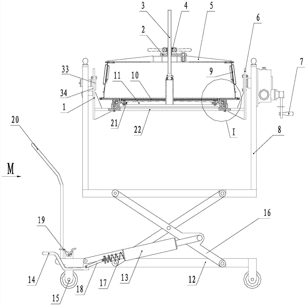
[0026] Such as Figure 1-Figure 11 As shown, a stress detection device for the rotary part of an aero-engine includes a hydraulic platform 12 with movable corner wheels 15 at the bottom, a vehicle frame 8 is arranged above the hydraulic platform 12, and the distance between the vehicle frame 8 and the hydraulic platform 12 is One end of the hydraulic cylinder 13 is hinged with the lifting bracket 16, and the other end is hinged with one end of the adapter block 18. The cylinder body of the hydraulic cylinder 13 is fixed on the hydraulic platform 12; one end of the hydraulic pedal 14 Hinged with the hydraulic platform 12, one end of the hydraulic pedal 14 hinged with the hydraulic platform 12 is hinged with the other end of the adapter block 18, and a return spring 17 is arranged between the hydraulic cylinder 13 and the adapter block ...


PUM


Abstract

The invention provides a stress detection device for a rotating member of an aero engine, and belongs to the technical field of stress detection of rotating members of aero engines. The stress detection device comprises a hydraulic platform, wherein movable casters are arranged on the bottom of the hydraulic platform, a frame is arranged on the upper portion of the hydraulic platform, the frame is connected with the hydraulic platform through a lifting support, one end of a hydraulic cylinder is hinged to the lifting support, the other end of the hydraulic cylinder is hinged to one end of a switchover block, and a cylinder body of the hydraulic cylinder is fixed to the hydraulic platform; one end of a hydraulic pedal is hinged to the hydraulic platform, and one end, hinged to the hydraulic platform, of the hydraulic pedal is hinged to the other end of the switchover block; a left bracket and a right bracket are arranged on two sides inside the frame respectively, the left bracket is connected with the frame through a bearing, the right bracket is fixedly connected with a handle mechanism arranged on the external of the frame through the frame, and the right bracket is connected with the frame through a bearing; the left bracket is fixedly connected with the right bracket through a horizontal bracket; a rolling bearing mechanism is arranged on the upper portion of the horizontal bracket, and a main supporting disc is arranged on the upper portion of the rolling bearing mechanism.

Description

technical field [0001] The invention belongs to the technical field of stress detection of aero-engine rotary parts, in particular to a stress detection device for aero-engine rotary parts. Background technique [0002] In order to evaluate the degree of satisfaction of the design indicators after the manufacturing of casings, rings, discs and other rotating parts, it is necessary to perform stress detection on the surface of the parts during the processing and the surface of the finished parts to grasp the stress distribution. In the process of stress detection, it is necessary to transport the parts to the designated place to detect the surface of the parts through fixed measuring equipment; Angle, and the detection tooling used on site is basically a V-shaped frame (made of wood and rubber), and the surface of the part with an angle needs to be adjusted repeatedly by filling things to ensure that the surface of the measured part is perpendicular to the detection probe; I...

Claims


Application Information

Patent Timeline
Patent Type & Authority Applications(China)
IPC IPC(8): G01L1/26
Inventor 唐秀梅王兴超刘娜李冬梅范秀华
Owner SHENYANG LIMING AERO-ENGINE GROUP CORPORATION
Why Eureka
Try Eureka