Circumferential pressurizing device for large-diameter Hopkinson pressure bar

A technology of Hopkinson pressure rod and pressure device, which is applied in the direction of measuring device, using stable tension/pressure to test the strength of materials, instruments, etc., can solve the problem of inability to clearly explain the structure and working principle of the hoop pressure device, Unable to test impact mechanical properties, unable to provide accurate and stable hoop pressure, etc., to improve test success rate and test accuracy, ensure accuracy, and reduce cost

Inactive Publication Date: 2014-03-05
AIR FORCE UNIV PLA
View PDF4 Cites 5 Cited by
  • Summary
  • Abstract
  • Description
  • Claims
  • Application Information

AI Technical Summary

Problems solved by technology

[0006] In order to overcome the existence of the existing hoop pressurization device or cannot provide accurate and stable hoop pressure, or cannot clearly explain the structure and working principle of the hoop pressurization device, or cannot perform hoop pressure on materials such as rocks and concrete Insufficiency of the impact mechanical property test under the action, the present invention proposes a kind of hoop pressurization device that is used for the large-diameter Hopkinson compression bar

Method used


Image

  • Circumferential pressurizing device for large-diameter Hopkinson pressure bar
  • Circumferential pressurizing device for large-diameter Hopkinson pressure bar
  • Circumferential pressurizing device for large-diameter Hopkinson pressure bar

Examples


Embodiment Construction

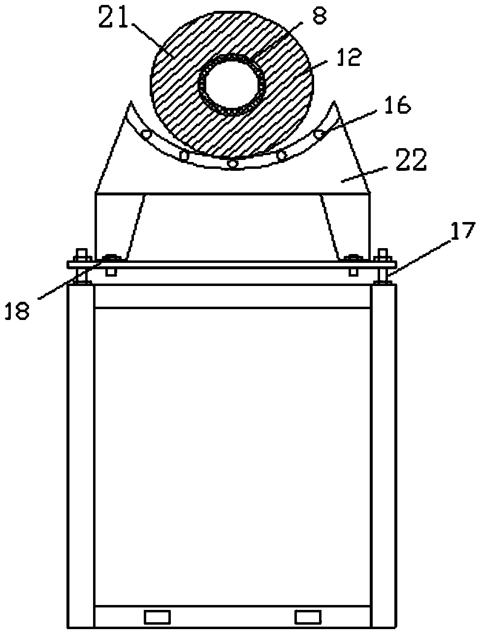
[0034] This embodiment is a hoop pressurizing device for a large-diameter Hopkinson bar, which includes a support 19 , a moving platform and a pressurizing cylinder 21 . The mobile platform is installed on the upper surface of the bracket 10, and the height of the mobile platform in the Z direction is adjusted by the bracket nut 17, and the displacement of the mobile platform in the Y direction is adjusted by the stand nut 18. The pressurized cylinder 21 is placed on the upper surface of the mobile platform, and moves in the X direction through the balls on the upper surface of the mobile platform.

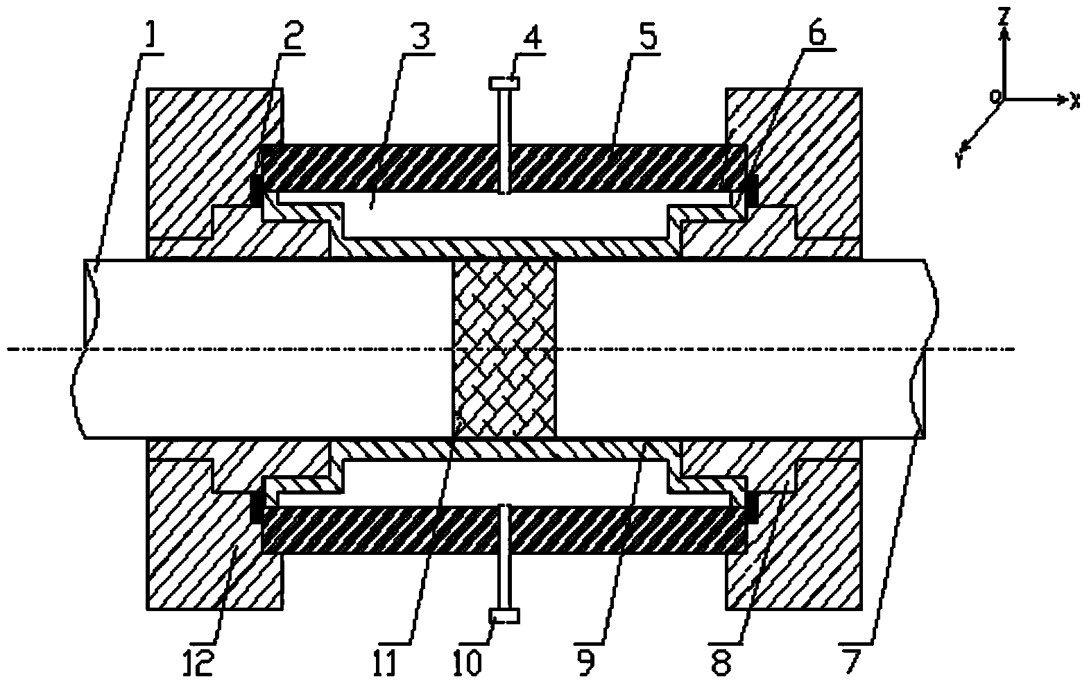
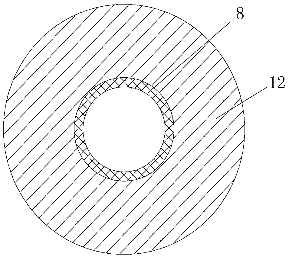
[0035] The pressurized cylinder 21 includes a hydraulic oil chamber 3 , an oil cylinder 5 , an oil-proof rubber sleeve 6 , a protective sleeve 9 , a pair of inner bushes 8 and a pair of outer sleeves 12 . Wherein, the outer peripheral surfaces of a pair of inner bushings 8 are stepped, and the peripheral surfaces of the outer two ends of the inner bushings are respectively the mat...


PUM

PropertyMeasurementUnit
diameteraaaaaaaaaa
particle diameteraaaaaaaaaa
diameteraaaaaaaaaa

Abstract

The invention discloses a circumferential pressurizing device for a large-diameter Hopkinson pressure bar. The circumferential pressurizing device is characterized in that a moving platform is arranged on the upper surface of a bracket and can move along the Z direction and the Y direction. A pressurizing cylinder body is arranged on the upper surface of the moving platform and can move along the X direction. One end of each of two inner bushings is arranged in each inner hole in the two ends of an oil-separating rubber sleeve; the other ends of the two inner bushings are respectively arranged in inner holes of two outer sleeves. The two inner bushings, an oil cylinder and the oil-separated rubber sleeve are fixed tightly by one pair of outer sleeves. A hydraulic oil chamber is formed between the inner surface of the oil cylinder and the outer surface of the oil-separated rubber sleeve. The circumference of the oil cylinder is provided with an oil inlet/pressure meter interface and an exhaust hole. The circumferential pressurizing device disclosed by the invention can be widely applied in indoor static-dynamic combined loading test of the Hopkinson pressure bar made of rock and concrete materials in the fields of civil air-defense engineering, geotechnical engineering and underground engineering and the like, and has the characteristics that the pressure application is accurate and uniform, the stability is high, the positioning of a test piece is accurate, the success ratio of the test is high and the service life is long and the like.

Description

technical field [0001] The invention relates to the field of material dynamic characteristic testing, in particular to a hoop pressure device for a large-diameter Hopkinson pressure bar. Background technique [0002] The separate Hopkinson compression bar test device is one of the important equipment for studying the dynamic mechanical properties of materials. It was originally used to study the mechanical properties of materials such as compression, splitting and torsion under uniaxial impact loading. In the construction of infrastructure such as tunnel engineering and civil air defense engineering, materials such as rocks and concrete are often under a certain static stress or ground stress before bearing dynamic loads, that is, the materials are in a three-dimensional stress state. Therefore, on the basis of the original Hopkinson compression bar test device, after a certain way of transformation, it can be used to study the mechanical response of materials under dynamic ...

Claims


Application Information

Patent Timeline
Patent Type & Authority Applications(China)
IPC IPC(8): G01N3/02G01N3/12
Inventor 苏灏扬许金余白二雷吕小聪罗鑫刘石高志刚任韦波王鹏
Owner AIR FORCE UNIV PLA
Why Eureka
Try Eureka