
Laboratory model testing device for tunnel excavation

An indoor model and tunnel excavation technology, applied in the direction of applying stable tension/pressure to test the strength of materials, can solve the problems of inconvenient operation, ignoring the role of initial support, and soil collapse around the excavated tunnel. The effects of promotion and application, good accuracy and convenient operation

Inactive Publication Date: 2014-03-05
HUNAN UNIV
View PDF5 Cites 41 Cited by
  • Summary
  • Abstract
  • Description
  • Claims
  • Application Information

AI Technical Summary

Benefits of technology

In this new system for studying tunneling processes during construction or other operations, it uses special materials that have lowered melting points than usual but stronger properties like steel plates when poured into holes underground. These material are then used to create an artificial wall called a tunnel shell. By controllably increasing temperature at specific locations within these walls, we aim to mimic realistic conditions such as pressure applied from outside sources over time without affecting any important aspects about how they work together.

Problems solved by technology

The technical problem addressed in this patents relates to accurately simulating tunnel excruptions during testing procedures without compromising its effectiveness or reliability. Current models are either too simplistic (overload) or fail to fully represent the forces involved when excavations occur around them.

Method used


Image

  • Laboratory model testing device for tunnel excavation
  • Laboratory model testing device for tunnel excavation

Examples


Embodiment Construction

[0023] The technical solutions of the present invention will be further described below in conjunction with the accompanying drawings and through specific implementation methods.

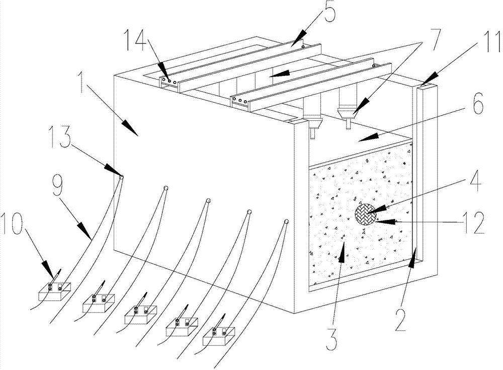
[0024] An indoor model test device for tunnel excavation, including a model box, a tunnel structure model 4, a loading device and an excavation device. The model box is composed of a trench 1 and a plexiglass plate 2, and an opening is arranged on one side of the trench 1. Both ends of the opening are provided with grooves 11, and the plexiglass plate 2 is fixed on one side of the opening of the trough 1 through the groove 11. The thickness of the plexiglass plate 2 is 10-15 mm, and it is colorless and transparent. A hole 12 slightly larger than the section of the tunnel is convenient for observing real-time changes and displacements of fillers around the tunnel structure model.

[0025] The model box is filled with a model test filler 3, the model test filler 3 is mainly composed of soil and stone,...


PUM


Abstract

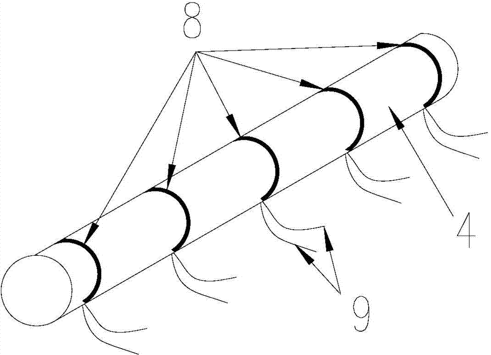
The invention discloses a laboratory model testing device for tunnel excavation. The laboratory model testing device comprises a model box, a tunnel structure model, a loading device and an excavation device, wherein the model box is composed of a floor trough and an organic glass plate, the organic glass plate is fixed on the opening surface of the floor trough through a groove; model testing fillers are padded in the model box; the tunnel structure model is made of rosin materials in a casting manner according to the ratio of similitude of an actual tunnel section, and is arranged in the middle of the model box; the loading device mainly comprises a counter-force beam, a steel plate and a hydraulic jack, and is arranged on the top of the model box; the excavation device mainly comprises a heating wire, a lead and a power supply switch, wherein the heating wire is arranged in the tunnel structure model. Due to the adoption of the testing device, the shape and size simulation in the tunnel excavation process can be performed conveniently, an excavation boundary can be well matched with a geometric boundary designed in advanced, the simulated tunnel excavation can be relatively well matched with an actual engineering; the testing device is simple in structure, convenient to operate, low in cost, and convenient to develop and apply.

Description


Claims


Application Information

Patent Timeline
Owner HUNAN UNIV
Learn More