
Apparatus for assisting makeup and an assembly constituted by such apparatus and apparatus for delivering makeup having a predetermined BRDF as selected by the apparatus for assisting makeup

a makeup and apparatus technology, applied in the field of apparatus for assisting makeup, can solve the problems of not being able to adapt to simulating the application of makeup, and not being able to take into account known apparatuses

Inactive Publication Date: 2004-10-26
LOREAL SA
View PDF14 Cites 63 Cited by
  • Summary
  • Abstract
  • Description
  • Claims
  • Application Information

AI Technical Summary

Benefits of technology

A particular object of the invention is to provide apparatus for assistance in makeup that makes it easy to simulate in realistic manner the application of a given makeup, e.g. on the face, for various lighting conditions.
The invention thus makes it possible to simulate optical effects specific to the makeup used, for example its mattness, its gloss, or its iridescence.
This makes it possible to simulate making up by means of a pencil, for example, which leaves a colored mark of greater or lesser intensity when it is pressed with greater or lesser force against the skin, the intensity corresponding to greater or smaller thicknesses and densities of the makeup.
Advantageously, the display means comprise stereoscopic display means so as to make the simulation more realistic.

Problems solved by technology

Known apparatuses do not make it possible to take account, amongst other things, of the lighting conditions in which a made-up subject is going to move around.
Finally, known apparatuses are poorly adapted at simulating the application of a makeup that masks little, is transparent, or diffuses slightly, and they take no account of the physical phenomena of light interaction between the skin and the cosmetic.
Thus, simulating the application of glossy or shiny makeup is not satisfactory.

Method used


Image

  • Apparatus for assisting makeup and an assembly constituted by such apparatus and apparatus for delivering makeup having a predetermined BRDF as selected by the apparatus for assisting makeup
  • Apparatus for assisting makeup and an assembly constituted by such apparatus and apparatus for delivering makeup having a predetermined BRDF as selected by the apparatus for assisting makeup
  • Apparatus for assisting makeup and an assembly constituted by such apparatus and apparatus for delivering makeup having a predetermined BRDF as selected by the apparatus for assisting makeup

Examples


Embodiment Construction

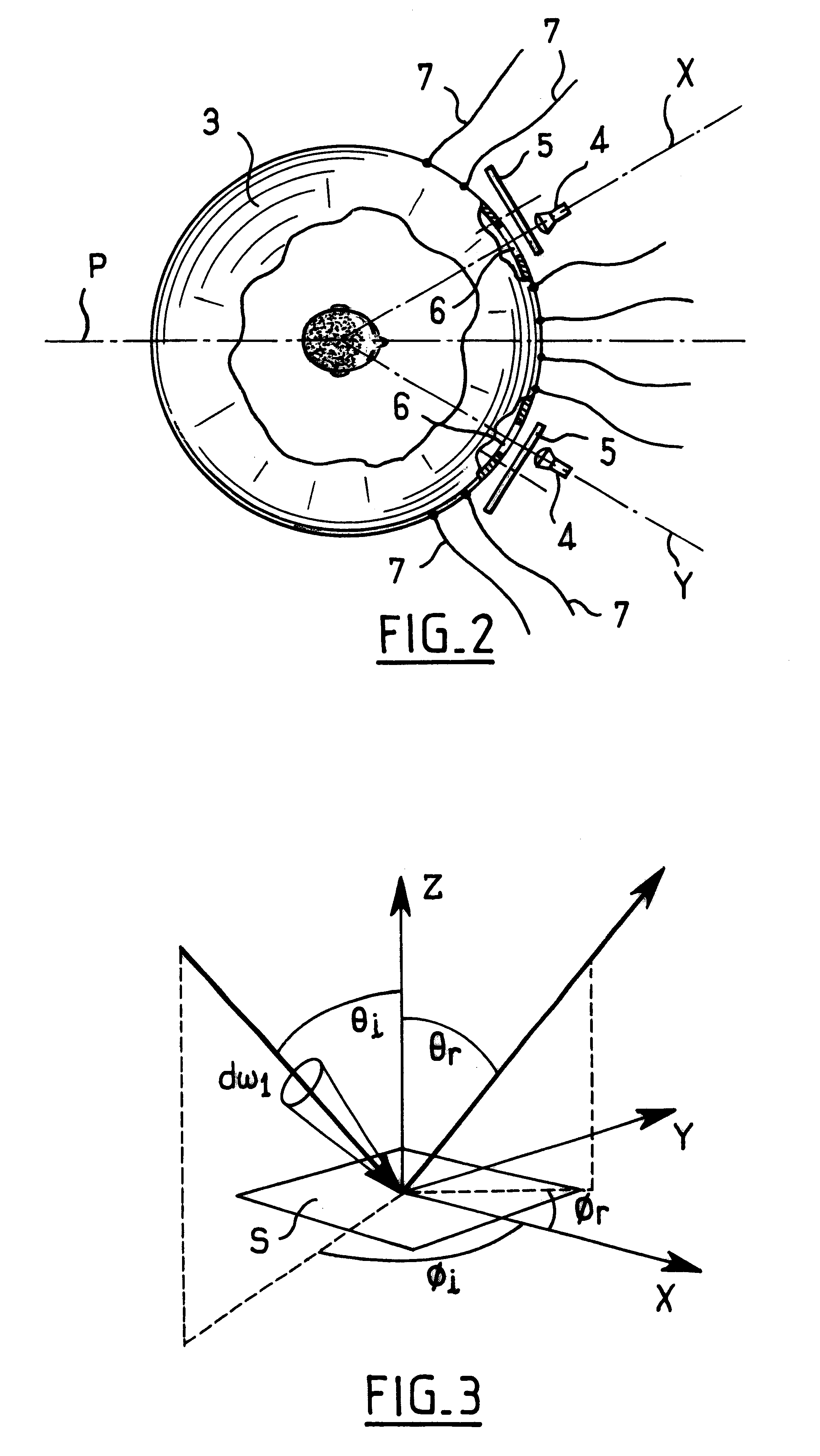
The direction of the returned light is defined by an angle .theta..sub.r relative to the axis Z, and .theta..sub.r relative to the axis X in the plane XY.

In the meaning of the invention, BRDF is defined by the following equation:

f.sub.r (.theta..sub.i,.phi..sub.i,.theta..sub.r,.lambda.).ident.L.sub.r (.theta..sub.r,100.sub.r,.lambda.) / [L.sub.i (.theta..sub.i,.phi..sub.i,.lambda.).multidot.cos.phi..sub. i.multidot.d.omega..sub.i ]

where L.sub.r is the energy luminance (or radiance) returned by an element of the surface and L.sub.i is the incident energy luminance (or irradiance) for the surface element.

For greater details concerning the parameters used in calculating BRDF, reference can usefully be made to the article entitled "Comprehensive physical model for light reflection" published in the journal Computer Graphics, 25 (4), August 1991, and to the article entitled "Reflection from layered surfaces due to subsurface scattering" published by the Computer Department of Princeton Uni...


PUM


Abstract

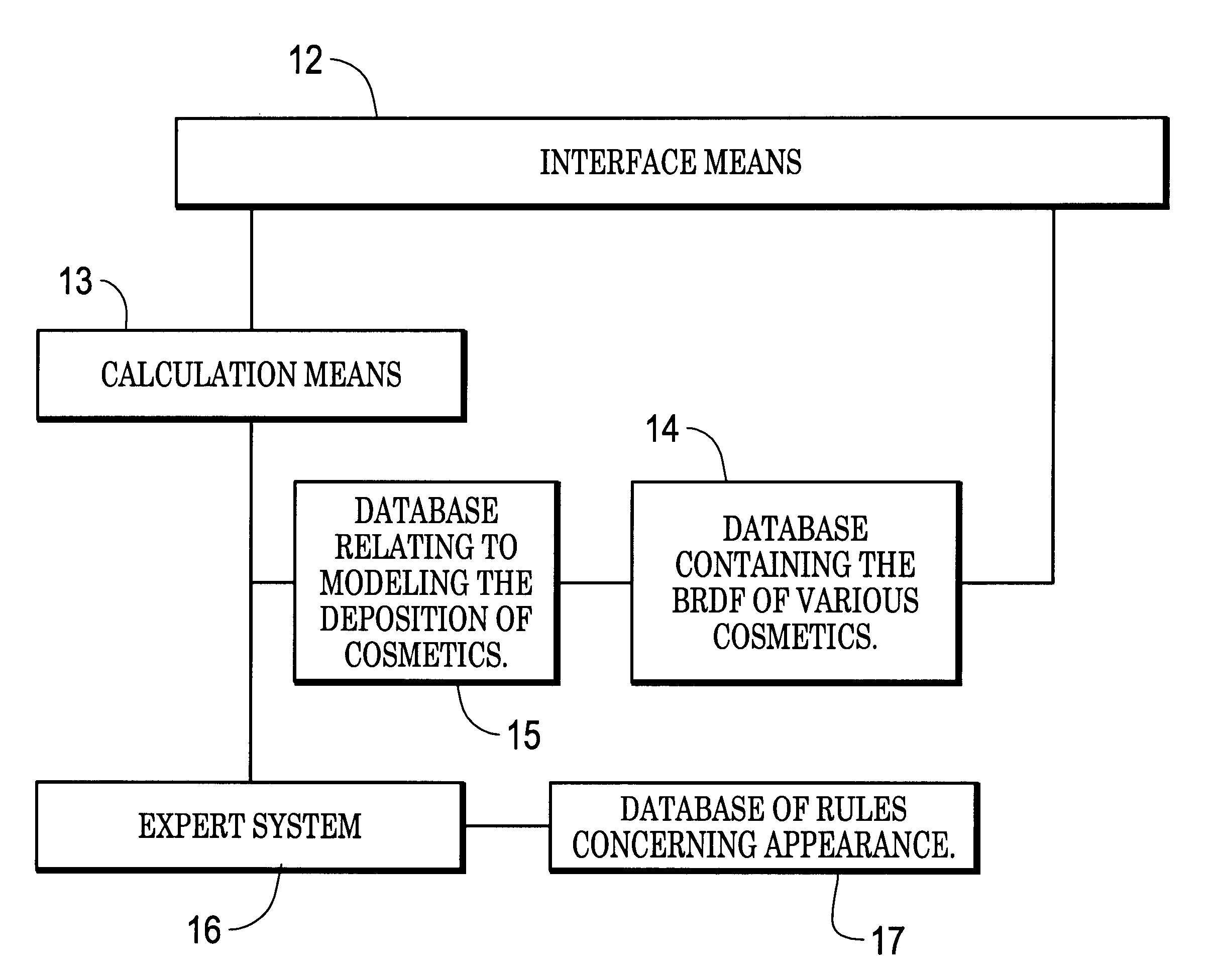
The apparatus for assistance in makeup includes a measurement unit for measuring local phenomena of light interaction with a zone to be made up and / or treated; a database relating to the BRDF of various cosmetic and / or care products; a selector unit enabling a product to be selected; a calculation unit for calculating the resulting BRDF to the zone virtually made up or treated with the product, on the basis of measurement previously taken and on the basis of information taken from the database and relating to the BRDF of the selected makeup product; and a display unit for displaying the zone virtually made up or treated in this way as a result of the previously calculated resulting BRFD.

Description

The present invention relates to apparatus for assisting makeup.Apparatus is known, in particular from international application WO 96 / 21201, comprising an acquisition unit for acquiring a 2D image of a face and image processing means to display the virtual application of makeup on the face.The Dec. 21, 1998 number of The Nikkei Weekly magazine discloses work enabling a made-up face to be displayed as a 3D image.Known apparatuses do not make it possible to take account, amongst other things, of the lighting conditions in which a made-up subject is going to move around.In particular, a person can make up at home under artificial light and then move outside, such that the rendering of the makeup is different.Finally, known apparatuses are poorly adapted at simulating the application of a makeup that masks little, is transparent, or diffuses slightly, and they take no account of the physical phenomena of light interaction between the skin and the cosmetic.Thus, simulating the applicati...

Claims


Application Information

Patent Timeline
Patent Type & Authority Patents(United States)
IPC IPC(8): G06T15/50A45D44/00
CPCG06T15/506G06T15/50
Inventor AUBERT, JOHANDAUGA, CHRISTOPHE
Owner LOREAL SA
Learn More