Electrostatic electron spectrometry apparatus

a technology of electron spectrometry and electron spectrometry, which is applied in the field of electron spectrometry, can solve the problems of difficult to achieve, difficult to use cma for many applications, and inferior energy resolution of 2 radian collection spectrometers, etc., and achieves the effects of improving energy resolution, shortening trajectory run time, and increasing complexity

Active Publication Date: 2011-09-06
NAT UNIV OF SINGAPORE
View PDF5 Cites 64 Cited by
  • Summary
  • Abstract
  • Description
  • Claims
  • Application Information

AI Technical Summary

Benefits of technology

[0009]Further simulations have shown that an accelerating pre-focusing lens improves the energy resolution for a given entrance angular spread by an order of magnitude (0.02% for ±6° entrance angular spread).
[0010]In these simulations, all field distributions and electron trajectory ray paths were simulated using Lorentz-2EM, a hybrid software that combines boundary element and finite element techniques. The boundary element method avoids well-known mesh generation / interpolation problems of the finite element method, especially difficult for curved boundaries. On the other hand, the finite element method was used for non-linear field solutions, such as those that arise in the presence of magnetic saturation, which are difficult to solve directly by boundary element methods. Both numerical techniques were coupled together, utilizing their relative strengths. In addition, an adaptive segment technique varied the density of charge segments on conductor surfaces, refining it according to local field strength. The subsequent improvement on field accuracy and shortening of trajectory run times for a given number of charge segments, allowed for modeling of problems of greater complexity. The software was able, for instance, to simulate electrostatic structures that are very small, and embedded in much larger conductor layouts. In the present context, this feature was used to plot accurate direct trajectory paths through an aperture slit, microns in size, placed within the fringe fields of a spectrometer measuring many centimeters. The use of a 5th order Runge-Kutta method in which the trajectory step-size varies according to local truncation error also helped in making this kind of problem much easier to simulate. The accuracy of all simulations were continually checked by repeating all results with smaller boundary segments and trajectory step sizes, ensuring that important ray tracing parameters, such as the rms value for the final focal point size at the spectrometer exit did not change significantly (by less than 1%).
[0011]To summarize, a toroidal electron energy spectrometer according to the present invention captures electrons in the full 2π azimuthal angular direction while at the same time having second-order focusing optics. Simulation results based upon direct ray tracing predict that the relative energy resolution of a spectrometer according to the present invention will be 0.146% and 0.0188% at input angular spreads of ±6° and ±3° respectively, which is comparable to the theoretically best resolution of the Cylindrical Mirror Analyzer (CMA), and an order of magnitude better than existing toroidal spectrometers. Also predicted for the spectrometer is a parallel energy acquisition mode of operation, where the energy bandwidth is expected to be greater than ±10% (20% total) of the pass energy. A spectrometer according to the present invention can allow for retardation of the pass energy without the need to incorporate auxiliary lenses.

Problems solved by technology

However, their focusing properties are usually based upon first-order optics, which makes their attainable energy resolution (for a given entrance angular spread) inferior to other types of 2π radian collection spectrometers such as the Cylindrical Mirror Analyzer (CMA), commonly used in Scanning Auger Microscopy (SAM).
These things are not easy to achieve with the CMA.
In practice, some other constraints make the CMA difficult to use for many applications, such as its sensitivity to specimen placement.
On the other hand, the finite element method was used for non-linear field solutions, such as those that arise in the presence of magnetic saturation, which are difficult to solve directly by boundary element methods.

Method used


Image

  • Electrostatic electron spectrometry apparatus
  • Electrostatic electron spectrometry apparatus
  • Electrostatic electron spectrometry apparatus

Examples


Embodiment Construction

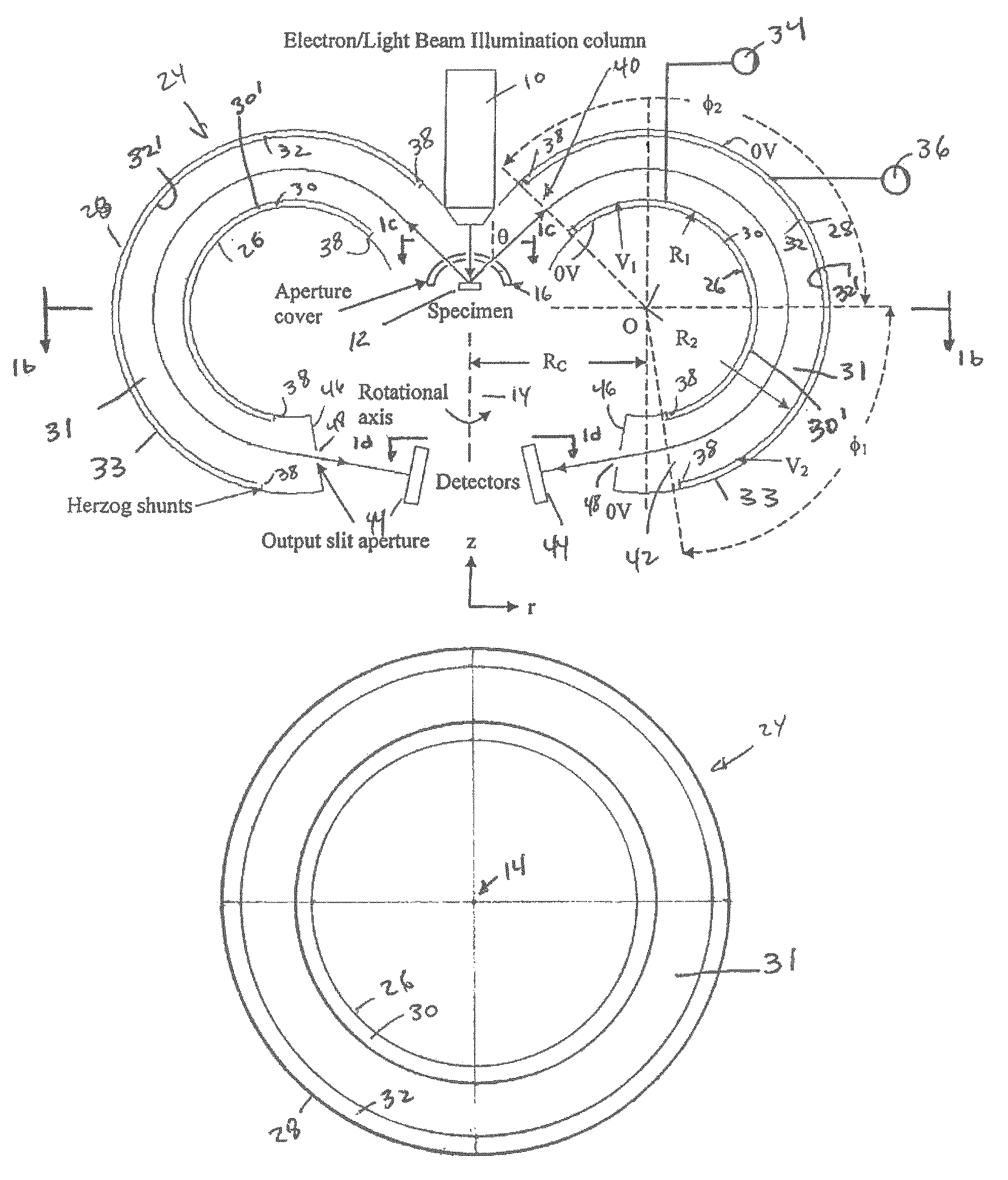
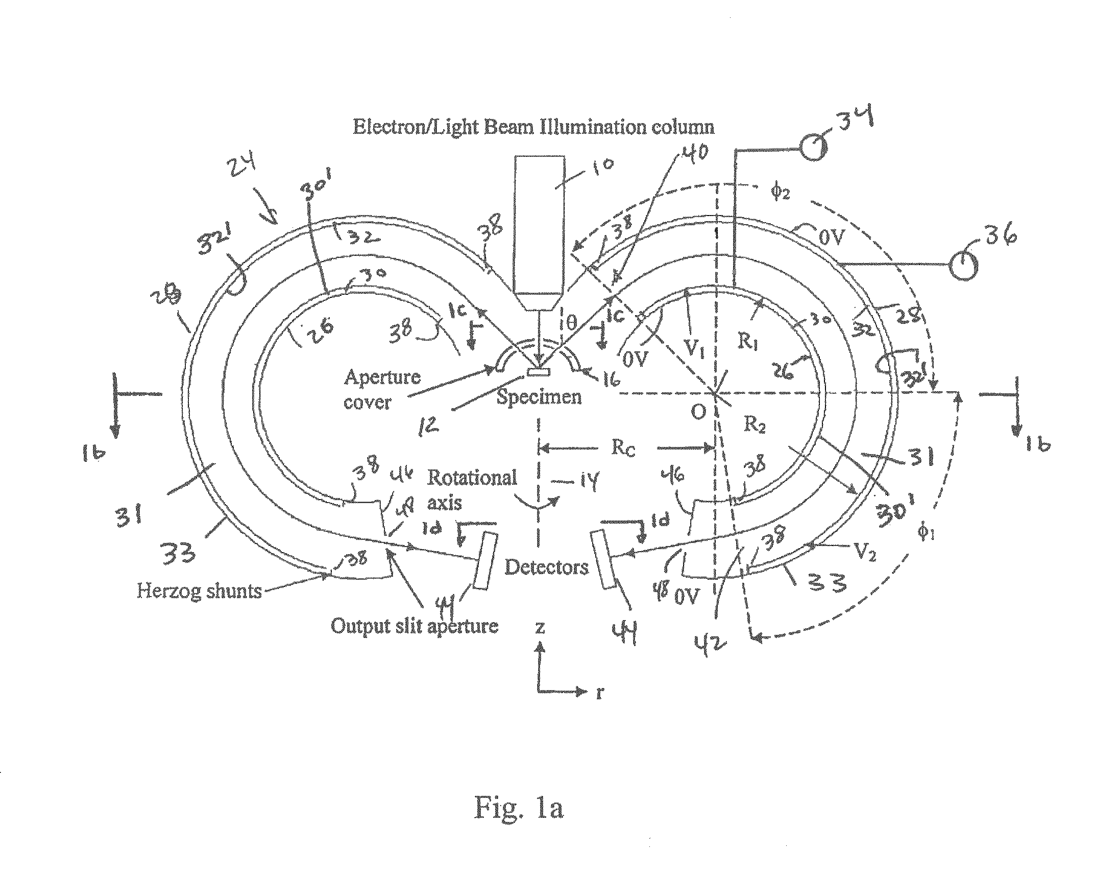
[0039]Referring to FIGS. 1a-1d, an electron spectrometry apparatus according to the present invention includes an emitter 10 which emits particles such as electrons or photons. Emitter 10 is arranged to bombard the surface of a specimen 12 with particles in order to generate a population of scattered electrons. The specimen may be a piece of semiconductor material, a metallic body, an organic sample or the like. Specimen 12 is preferably positioned on a platform, which is rotated about a rotation axis 14 in a clockwise or a counter-clockwise direction. Preferably, the beam of particles emitted from emitter 10 travel in a direction that is generally aligned with rotation axis 14. As is well known, the bombardment of specimen 12 causes the generation of scattered electrons from specimen 12 which travel in all directions. In order to select the direction of scattered electrons a cover 16 is placed over specimen 12. Specifically, cover 16 includes an annular slit 18 the width of which i...


PUM

PropertyMeasurementUnit
angleaaaaaaaaaa
energyaaaaaaaaaa
step-sizeaaaaaaaaaa

Abstract

An apparatus for spectrometry that includes a spectrometer configured for second order focusing and capable of 2π azimuthal collection.

Description

CROSS-REFERENCE TO RELATED APPLICATION[0001]This application is based on and claims benefit of U.S. Provisional Application Ser. No. 61 / 080,345, filed on Jul. 14, 2008, entitled A SECOND-ORDER FOCUSING TOROIDAL ELECTRON ENERGY SPECTROMETER, to which a claim of priority is hereby made and the disclosure of which is incorporated by reference.BACKGROUND AND SUMMARY OF THE INVENTION[0002]The present invention relates to spectrometry and more particularly to an electrostatic electron spectrometry apparatus that includes a toroidal spectrometer configured for second order focusing at a detector plane. Toroidal electron energy spectrometers have been used for angular photoemission studies, electron scattering experiments, and the capture of the backscattered electron (BSE) spectrum in the Scanning Electron Microscope (SEM). Toroidal Spectrometers have the desirable feature of possessing rotational symmetry, and are naturally able to collect electrons in the full 2π azimuthal direction. How...

Claims


Application Information

Patent Timeline
Patent Type & Authority Patents(United States)
IPC IPC(8): H01J47/00G01N23/00
CPCH01J49/48
Inventor KHURSHEED, ANJAM
Owner NAT UNIV OF SINGAPORE
Why Eureka
Try Eureka