Gamma-ray camera system

a camera system and gamma-ray technology, applied in the field of gamma-ray camera systems, can solve the problems of poor energy resolution, variance in the scintillation efficiency of the crystal itself, and worse resolution in the resulting image, and achieve the effect of higher energy resolution

Inactive Publication Date: 2009-03-17
SYMETRICA
View PDF20 Cites 12 Cited by
  • Summary
  • Abstract
  • Description
  • Claims
  • Application Information

AI Technical Summary

Benefits of technology

[0032]By deconvolving detector response functions which are dependent on individual detector pixels from the observed energy spectra, much higher energy resolution can be obtained when compared to previously described systems. The higher energy resolution allows, for example, improved images to be formed where there is significant Compton scattering in a source being imaged. The higher energy resolution also allows radioactive sources emitting gamma-ray photons at different, though similar, energies to be better distinguished. Whereas with previous systems, it has generally been necessary to make sequential observations of a subject in order to study how different pharmaceuticals marked with different radioactive tracers are taken up in a body, improved energy resolution allows different radioactive tracers to be simultaneously imaged and separated in a single observation.
[0034]By providing a separate detector response function for each individual detector pixel, the most accurate mapping of the detector response to detector pixel can be obtained.
[0036]By providing a number of detector response functions which is fewer than the number of detector pixels, a compromise can be made between the benefits of providing individual detector response functions for each detector pixel, and the benefits of working with a reduced number of detector response functions, for instance reduced storage requirements.
[0039]This method provides much higher energy resolution than previous methods of processing data from gamma-ray camera systems and correspondingly provides similar benefits to those of the first aspect of the invention described above.

Problems solved by technology

However, because of Compton scattering within the sample 4, the resolution in a resulting image is worse than this.
This relatively poor energy resolution is significantly worse than that predicted by photon-statistics alone and is due to several factors.
One effect is the variance in the scintillation efficiency of the crystal itself, this is energy dependent and cannot be corrected for simply.
Another effect is the non-uniformity of the response of the photo-multiplier tubes.
This means that it is not normally possible to make simultaneous observations of multiple radioactive tracers, and sequential observations must be made.
In cases where the field-of-view includes only a monochromatic source of gamma-ray emission, the poor energy resolution can still lead to degradation in derived diagnostic images where the source is embedded in a body.
One disadvantage of this choice of energy is that the gamma-ray photons have a relatively high probability of scattering within the surrounding body before being viewed by the gamma-ray camera.
As a consequence, an additional source of background noise in introduced throughout the image.
The additional background noise not only leads to a reduction in the sensitivity of the camera due to the reduced signal-to-noise ratio in each pixel, but also impacts on the spatial resolution of derived images as a Compton scattered halo becomes associated with each portion of the gamma-ray source due to the non-direct detection events.
However, the poor energy resolution of scintillator crystal based gamma-ray camera systems is not able to provide suitable energy discrimination at 140 keV to make this an efficient process.
This leads to derived diagnostic images with a poor signal-to-noise ratio.
As outlined above, the inclusion of a significant fraction of Compton scattered detection events leads to relatively poor spatial resolution in the generated image due to the Compton scattered halo appearing to surround each element of the gamma-ray source. FIG. 4C shows the result of using a narrow energy window such as the one marked W2 in FIG. 3.
This causes the image to appear faint against a relatively high background noise level.
However, there are a number of disadvantages associated with this type of design.
For example, each detector pixel requires a separate read-out electronics channel, the detection efficiency is relatively low and the camera costs are high.
However, this design again requires significantly increased complexity in the read out electronics in comparison to other types of gamma-ray camera system, such as the kind discussed above.

Method used


Image

  • Gamma-ray camera system
  • Gamma-ray camera system
  • Gamma-ray camera system

Examples


first embodiment

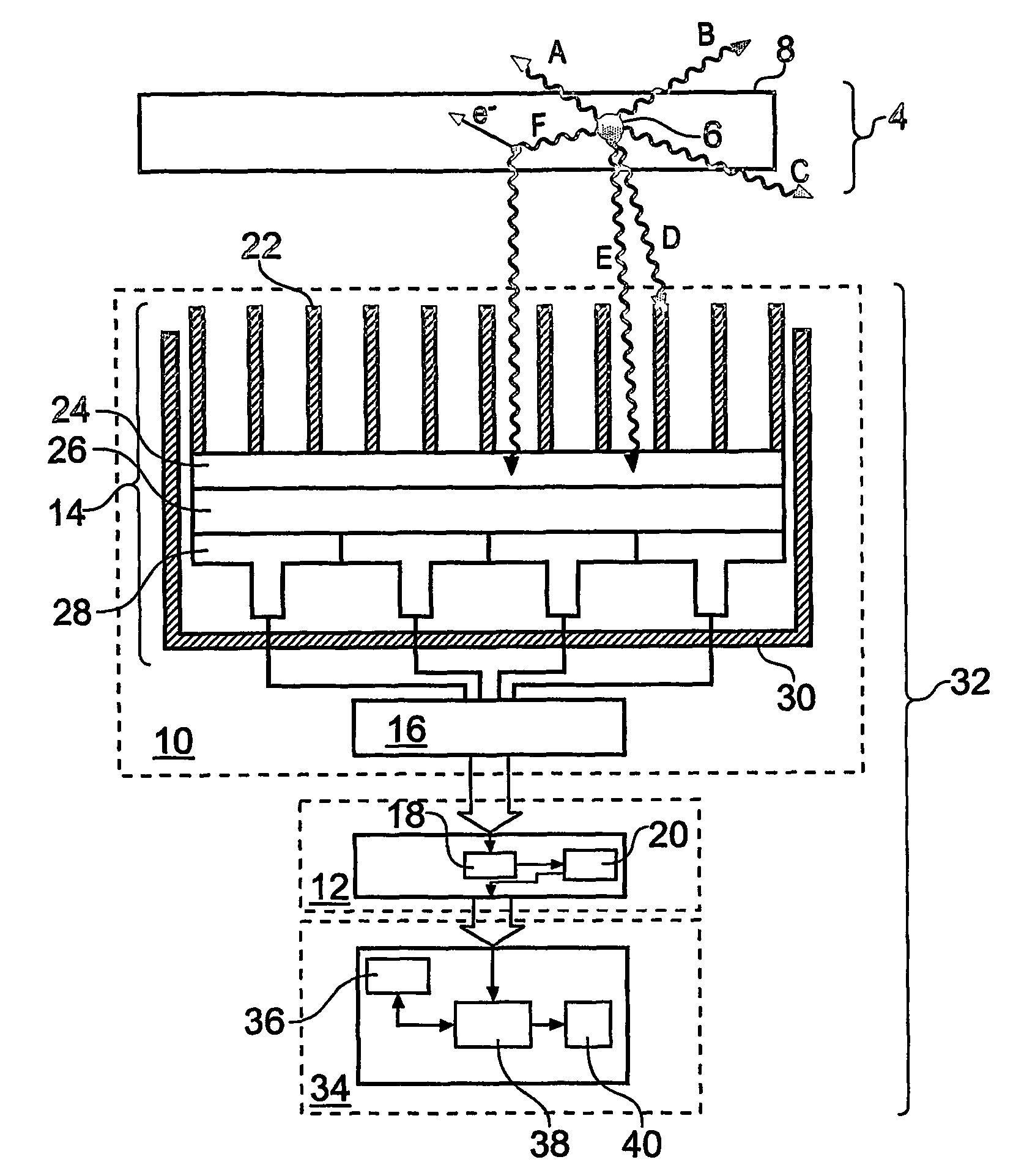
[0058]FIG. 5 schematically shows in vertical cross-section a gamma-ray camera system 32 according to the invention. Many of the features of the gamma-ray camera system 32 shown in FIG. 5 are similar to and will be understood from the correspondingly numbered features shown in FIG. 1 and described above. However, the gamma-ray camera system 32 additionally includes a spectra processing component 34. The spectra processing component includes a store of detector response functions 36, a spectra processor 38 and a data storage component 40. The functionality of the spectra processing component in this example is provided by a suitably configured general purpose computer. However, an application specific integrated circuit (ASIC), a field programmable gate array (FGPA) or a digital signal processor (DSP) may also be employed.

[0059]The spectra processing component 34 is arranged to read the observed data array I(X, Y, E) from the data storage component 20 in the energy spectra accumulatin...

second embodiment

[0072]FIG. 9 is a flow chart which schematically details some of the operational steps performed within a spectra processing component employed in a gamma-ray camera system of the invention. As above, the gamma-ray camera imager provides a square array of XTOT by YTOT detector pixels. At T1, the observed data array I(X, Y, E) corresponding to a prior observation is read from the data storage element 20 shown in FIG. 5. In this embodiment, the spectra processing component is configured to process the spectra associated with each detector pixel in parallel. A separate process thread operates for each individual detector pixel, this removes the need to iterate seen FIG. 8, and provides for significantly faster processing. In the first step of one process thread, labelled T2 in FIG. 9, the detector pixel corresponding to X=1 and Y=2 is selected. At the same time, threads corresponding to all other detector pixels are similarly instigated. In T3, the next step in the thread started at T...


PUM


Abstract

A scintillator crystal (26) based gamma-ray camera system is described. The gamma-ray camera system includes a spectra processing component for (34) providing improved energy resolution over that seen in conventional gamma-ray camera systems. The spectra processing component operates to deconvolve detector response functions from observed energy spectra on a pixel by pixel basis. The pixel dependent to detector response functions are obtained by a combination of theoretical simulation, and empirical calibration. By deconvolving pixel specific detector response functions, variations in response of a gamma-ray camera system across its image plane can be accounted for. This offers significant improvements in energy resolution and many of the problems associated with conventional gamma-ray camera systems are reduced. For example, the improved energy resolution allows better rejection of photons associated with Compton scattering events occurring in a source being imaged. This is because a narrower energy window filter can be used without rejecting a significant fraction of non-Compton scattered photons. The spectra processing component can be easily implemented with different types of gamma-ray imagers, for example Anger-type cameras, and may also be retroactively fitted to existing gamma-ray camera systems.

Description

[0001]This application is a national phase of International Application No. PCT / GB2004 / 000982 filed Mar. 9, 2004 and published in the English language.BACKGROUND OF THE INVENTION[0002]The invention relates to gamma-ray camera systems, in particular to spectral processing of data in gamma-ray camera systems.[0003]FIG. 1 schematically shows in vertical cross-section a gamma-ray camera system 2 viewing a sample 4. In this case the sample comprises a point-like gamma-ray source 6 embedded within an extended body 8. The gamma-ray camera system comprises a gamma-ray camera 10 and an energy spectra accumulating component 12. The gamma-ray camera 10 is an Anger-type camera [1]. This is a type widely used as a diagnostic tool in nuclear medicine. The gamma-ray camera 10 includes a gamma-ray imager 14 coupled to a detector read-out component 16. The energy spectra accumulating component includes an energy spectra accumulator 18 and a data storage component 20.[0004]The gamma-ray imager 14 inc...

Claims


Application Information

Patent Timeline
Patent Type & Authority Patents(United States)
IPC IPC(8): G01T1/20G01T1/164
CPCG01T1/1642G01T1/1644A61B6/4258A61B6/00G01T1/20
Inventor RAMSDEN, DAVID
Owner SYMETRICA
Why Eureka
Try Eureka