
Calorimeter

a radiation detector and calibrator technology, applied in the field of superconducting radiation detectors, can solve the problems of a large transition width, the resistor cannot be smaller than the absorber area, and cannot be below 100 ev

Inactive Publication Date: 2004-02-12
HITACHI HIGH TECH SCI CORP
View PDF5 Cites 12 Cited by
  • Summary
  • Abstract
  • Description
  • Claims
  • Application Information

AI Technical Summary

Benefits of technology

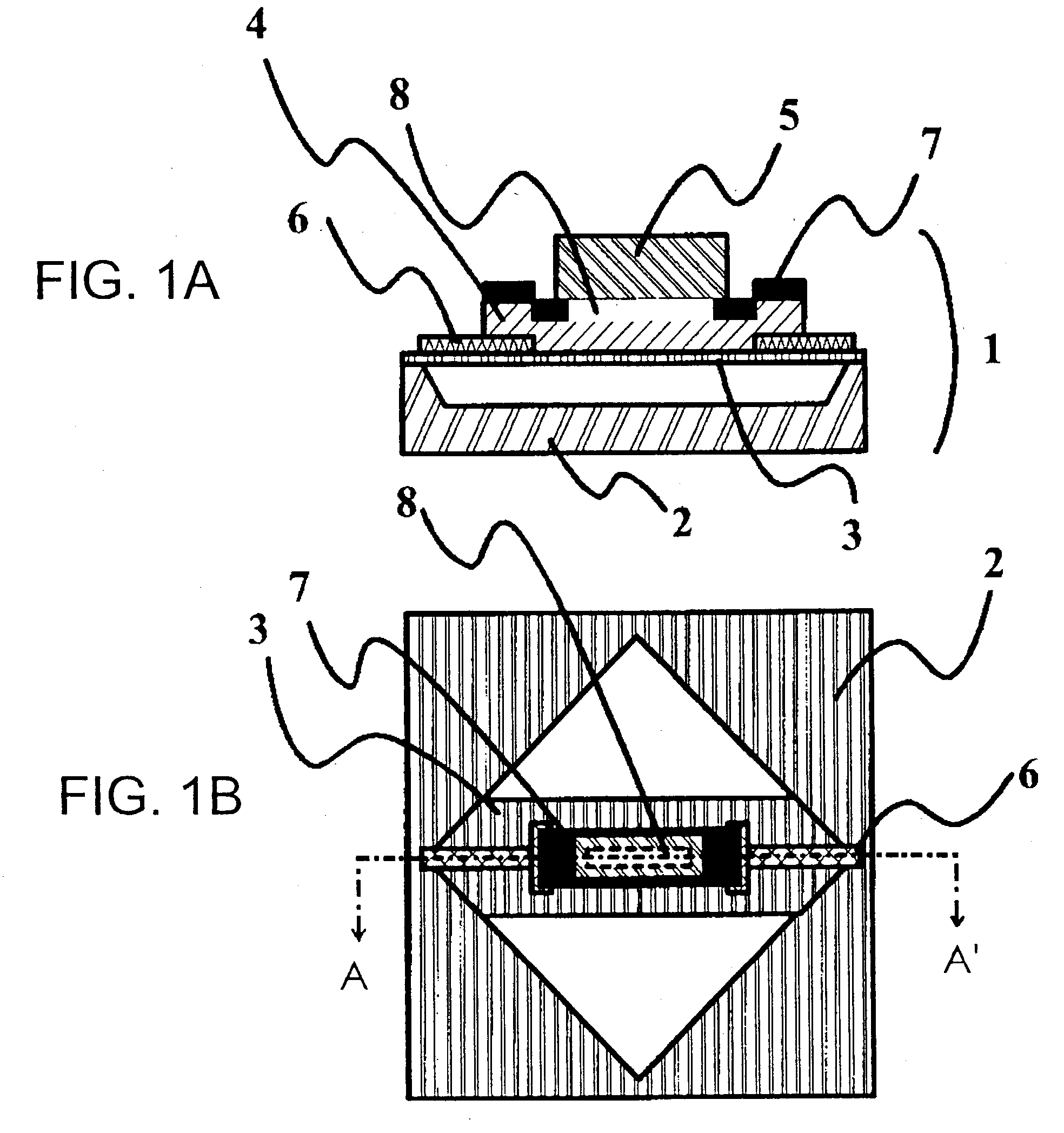
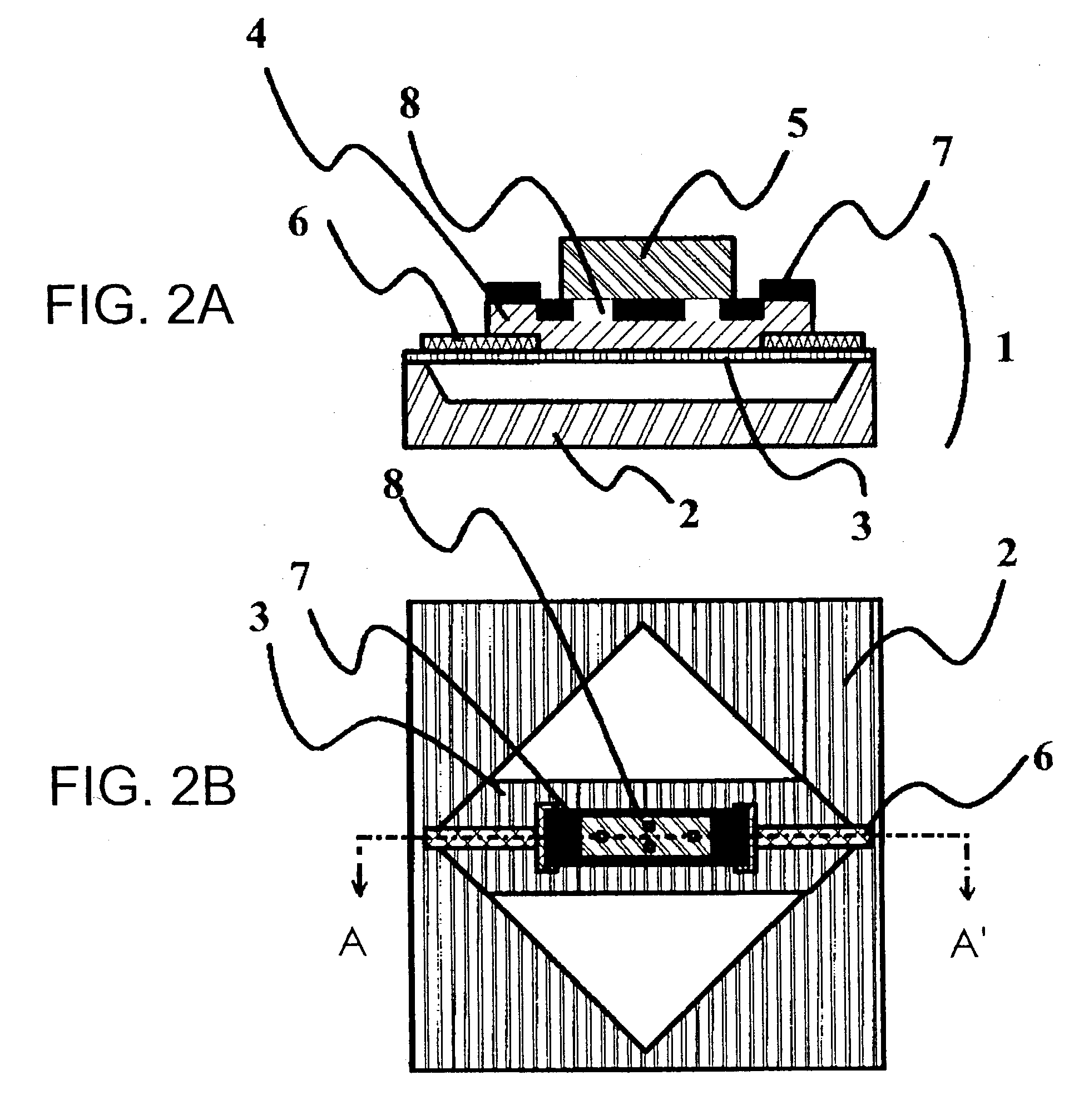
[0032] (1) As described above, by using an insulating film provided with a penetrating hole, hot electrons generated by absorption of X-rays by an absorber diffuse inside the absorber quickly and uniformly be able to raise the temperature of a resistor through the hole and restrict the variation of the peak values of the waveforms of current pulses generated in the resistor. Further, the insulating film is provided between the absorber and the resistor, thereby maintaining the superconductivity of the resistor under the insulating film even the case that the absorber and the resistor are virtually of an equal size. Thus, the invention provides a calorimeter that can restrict the variation of the peak values of current waveforms more and has a high energy resolution than a calorimeter according to the related art.[0033] (2) In case that there are a plurality of penetrating holes described above, at least two holes are arranged parallel to the direction of the current, most of the current flowing in the calorimeter flows in the resistor. Therefore, in case that the absorber is a thick metal body, the resistance value of the absorber is particularly low so that the resistance value of the calorimeter is lowered. By a low resistance value of the calorimeter and a low current flowing, the Joule heat generated in the calorimeter can be lowered. The low Joule heat makes the temperature distribution inside the calorimeter almost uniform. The uniform temperature distribution decreases the fluctuation of temperature inside the calorimeter, and the energy resolution of the calorimeter is improved.[0034] (3) In case that four holes are provided such that two of them are arranged parallel to the current and the other two are arranged vertically, hot electrons generated by absorbing X-rays can warm the resistor uniformly through the holes and restrict the variation of peak values of current pulses generated in the resistor. Thus, a calorimeter having a high energy resolution can be provided.[0035] (4) In the case that the insulating film is made of a material that cannot be etched by hydrogen fluoride, when the material constituting the calorimeter is etched by hydrogen fluoride, an essential part of the calorimeter is protected from etching by hydrogen fluoride, making it possible to make the calorimeter stably in a process. Particularly, tantalum pentoxide can be easily formed into a film by sputtering at a room temperature, which makes the process easier.

Problems solved by technology

However, since energy resolution depends on the energy gap of a semiconductor, it cannot be below 100 eV.
Therefore, the area of the resistor cannot be smaller than that of the absorber.
In case that the size of the resistor is fixed, the transition temperature of a calorimeter having an absorber is lower than that of a calorimeter having no absorber, which also causes a problem of a large width of transition.

Method used


Image

  • Calorimeter
  • Calorimeter
  • Calorimeter

Examples


first embodiment

[0021] First Embodiment

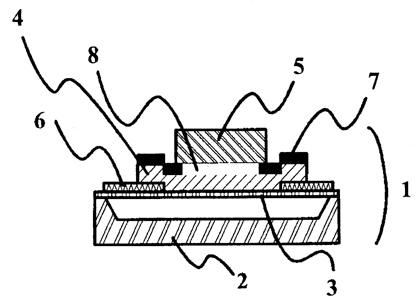
[0022] FIGS. 1A and 1B are schematic diagrams of a calorimeter, according to a first embodiment of the invention, provided with an insulating film 7 between a resistor 4 and an absorber 5. FIG. 1B is a plan view, and FIG. 1A is a cross-sectional view taken along line A-A' of FIG. 1B. The absorber 5 for absorbing X-rays is superimposed on the resistor 4 of which the resistance value is changed by heat generated by the absorber. The resistor 4 is connected to an external current detector through superconducting wires 6. The resistor 4 is superimposed on a membrane 3. The resistor 4 is constituted by a superconductor and a Joule heat generated by a current that is steadily flown in the resistor 4 and a Joule heat generated by the absorber 5 are thermally balanced and transfer in the membrane.

[0023] In the calorimeter 1, the membrane 3 is provided on a board 2, and the resistor 4, the absorber 5, and the superconducting wires 6 are superimposed on the membrane 3. ...

second embodiment

[0028] Second Embodiment

[0029] FIG. 2B is a schematic diagram of a calorimeter, according to a second embodiment of the invention, provided with four holes, where in two of them are arranged parallel to the direction of a current, and the other two are arranged vertically. FIG. 2A is a cross-sectional view taken along line A-A' of FIG. 2B.

[0030] Hot electrons generated in an absorber 5 by absorption of X-rays isotropically diffuse inside the absorber. To raise the temperature of a resistor 4 uniformly, it is required that the hot electrons having diffused in the absorber 5 reach the resistor 4 as quickly as possible and uniformly diffuse in the resistor 4. Two holes out of the four holes 8 are arranged parallel to the current, the other two holes are arranged vertically, and thus the hot electrons can quickly reach inside the resistor 4, no matter where inside the absorber the hot electrons are generated. Since it is electrons that primarily transfer heat in the resistor 4, the elec...


PUM


Abstract

A superconducting radiation detector uses the abruptness of a superconducting transition edge, converts a slight heat generated by an X-ray into a high signal current, and uses an electrothermal self-feedback mechanism, thereby having a high energy resolution and a high counting rate. In a calorimeter that includes an absorber for absorbing X-rays, a resistor provided under the absorber, a resistance value thereof being changed by heat generated in the absorber, superconducting wires connecting the resistor and an external current detector, and a membrane on which the resistor is superimposed, the resistor being constituted by a superconductor, the calorimeter allowing Joule heat generated by steadily flowing a current in the resistor and the heat generated in the absorber to be thermally balanced and transfer in the membrane, an insulating film is provided between the resistor and the absorber, the film having a hole penetrating the film in the thickness direction.

Description

[0001] 1. Field of the Invention[0002] The present invention relates to a superconducting radiation detector having a high energy resolution and a high counting rate by using the abruptness of superconducting transition edge, converting a slight heat generated by an X-ray into a high signal current, and using an electrothermal self-feedback mechanism.[0003] 2. Description of the Related Art[0004] Microcalorimeters using a superconducting transition edge having a higher energy resolution and a higher counting rate (hereinafter referred to as "microcalorimeter") than detectors using semiconductors, according to the related art, used for analysis of elements or impurity tests are attracting attention. Energy Disperse Spectroscopies (EDS) are known, as detectors according to the related art using semiconductors, and can quickly carry out analysis of elements for a wide range of energy. However, since energy resolution depends on the energy gap of a semiconductor, it cannot be below 100 ...

Claims


Application Information

Patent Timeline
IPC IPC(8): G01K7/00G01K17/00G01T1/12G01T1/26G01T1/36H01L39/00
CPCG01K17/00G01K7/006
Inventor TANAKA, KEIICHIMOROOKA, TOSHIMITSUNAKAYAMA, SATOSHI
Owner HITACHI HIGH TECH SCI CORP
Learn More