
PML boundary condition absorbing method based on second-order partial differential wave equation

A second-order partial differential and wave equation technology, applied in seismic signal processing and other directions, can solve problems such as inability to deal with incident angle reflection problems and complex implementation.

Active Publication Date: 2014-03-05
PETROCHINA CO LTD
View PDF3 Cites 14 Cited by
  • Summary
  • Abstract
  • Description
  • Claims
  • Application Information

AI Technical Summary

Problems solved by technology

The first type is the sponge absorption boundary condition, which gradually attenuates the wave field in a medium with a certain thickness, such as the damping absorption boundary condition; the second type is the paraxial approximate absorption boundary condition based on the wave equation, which is essentially a one-way The shortcoming is that it cannot deal with the reflection problem with a large incident angle; the third type is the PML absorption boundary condition based on the wave equation. Since the complex wave impedance between different perfectly matched layers is the same, the wave is There is no reflection but only attenuation when propagating between
[0005] However, the existing perfectly matched layer absorbing boundary condition is only suitable for the numerical simulation of the first-order partial differential wave equation, and the split perfectly matched layer absorbing boundary condition is mainly used
In the calculation process, in order to save calculation and storage, the existing technology often splits the wave field in the area of ​​the perfect matching layer. For three-dimensional space problems, the areas that need to be considered include 6 face areas, 12 edge areas and 8 corners. point area, resulting in a very complex implementation

Method used


Image

  • PML boundary condition absorbing method based on second-order partial differential wave equation
  • PML boundary condition absorbing method based on second-order partial differential wave equation
  • PML boundary condition absorbing method based on second-order partial differential wave equation

Examples


Embodiment Construction

[0076] In order to make the object, technical solution and advantages of the present invention clearer, the present invention will be further described in detail below in conjunction with the embodiments and accompanying drawings. Here, the exemplary embodiments and descriptions of the present invention are used to explain the present invention, but not to limit the present invention.

[0077] The specific embodiment of the present invention will be further described in detail below in conjunction with the accompanying drawings.

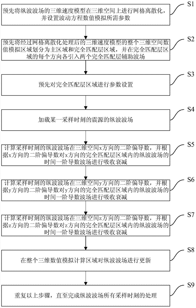
[0078] see figure 1 As shown, the method of the PML absorbing boundary condition based on the second-order partial differential wave equation of the embodiment of the present invention comprises the following steps:

[0079] Step S1, discretize the three-dimensional velocity model of the longitudinal wave field in three-dimensional space in advance, and set the parameters required for the numerical simulation of the wave equation. The required para...


PUM


Abstract

The invention provides a PML boundary condition absorbing method based on a second-order partial differential wave equation. The method includes the first step of loading a longitudinal wave field of an earthquake source at a certain sampling moment, the second step of calculating a second-order partial derivative of the longitudinal wave field in a certain direction of a three-dimensional space at the sampling moment, and carrying out attenuation by absorption of a time first-order derivative wave field of the longitudinal wave field in a perfectly matched layer area in the direction according to the second-order partial derivative in the direction, the third step of repeating the second step, and carrying out attenuation by absorption of time first-order derivative wave fields of the longitudinal wave field in perfectly matched layer areas in the other two directions of the three-dimensional space at the sampling moment respectively, and the fourth step of repeating the preceding steps until processing of the longitudinal wave fields at all sampling moments is finished. By the adoption of the method, achieving complexity of boundary condition absorbing on a perfectly matched layer is low, and the calculation storage amount is small.

Description

technical field [0001] The invention relates to a wave equation numerical simulation technology in the field of geophysical exploration, in particular to a method for absorbing boundary conditions of a PML (perfect matched layer) based on a second-order partial differential wave equation. Background technique [0002] Seismic wave numerical simulation technology has been widely used in the field of geophysical exploration. It is often used to design seismic acquisition and observation systems, study the seismic wave response of complex reservoirs, realize seismic wave reverse time migration imaging and full waveform inversion velocity modeling technology, etc. [0003] In wave equation numerical simulation technology, an important research content is absorbing boundary conditions. In the real world, the boundary of the velocity medium model may be infinite; when using a computer for numerical simulation, only the infinite model can be truncated, which will lead to unwanted s...

Claims


Application Information

Patent Timeline
IPC IPC(8): G01V1/28
Inventor 秦臻宋建勇马晓宇宋雪娟
Owner PETROCHINA CO LTD
Learn More