Unlock instant, AI-driven research and patent intelligence for your innovation.

Rigid core

A technology of rigid core and core body, applied in the field of rigid cores, can solve the problems of difficulty in determining the positioning of core segments and core segments, not easy to operate, and difficult to automatically remove bolts, etc., to achieve the effect of improving efficiency

Active Publication Date: 2014-03-05
SUMITOMO RUBBER IND LTD
View PDF4 Cites 0 Cited by
  • Summary
  • Abstract
  • Description
  • Claims
  • Application Information

AI Technical Summary

Problems solved by technology

[0009] However, in this structure, automatic removal of the bolt (e) is not easy to achieve; moreover, there must be many bolts to be tightened
Therefore, the disassembly and assembly operation of the rigid core (a) is a lot of work and thus not very operable
In addition, it is difficult to determine the positioning of each of the core segments (c), thus prone to inaccurate
Therefore, it is difficult to assemble a rigid core with high precision and stability (a)

Method used


Image

  • Rigid core
  • Rigid core
  • Rigid core

Examples


Embodiment Construction

[0061] Hereinafter, embodiments of the present invention will be described.

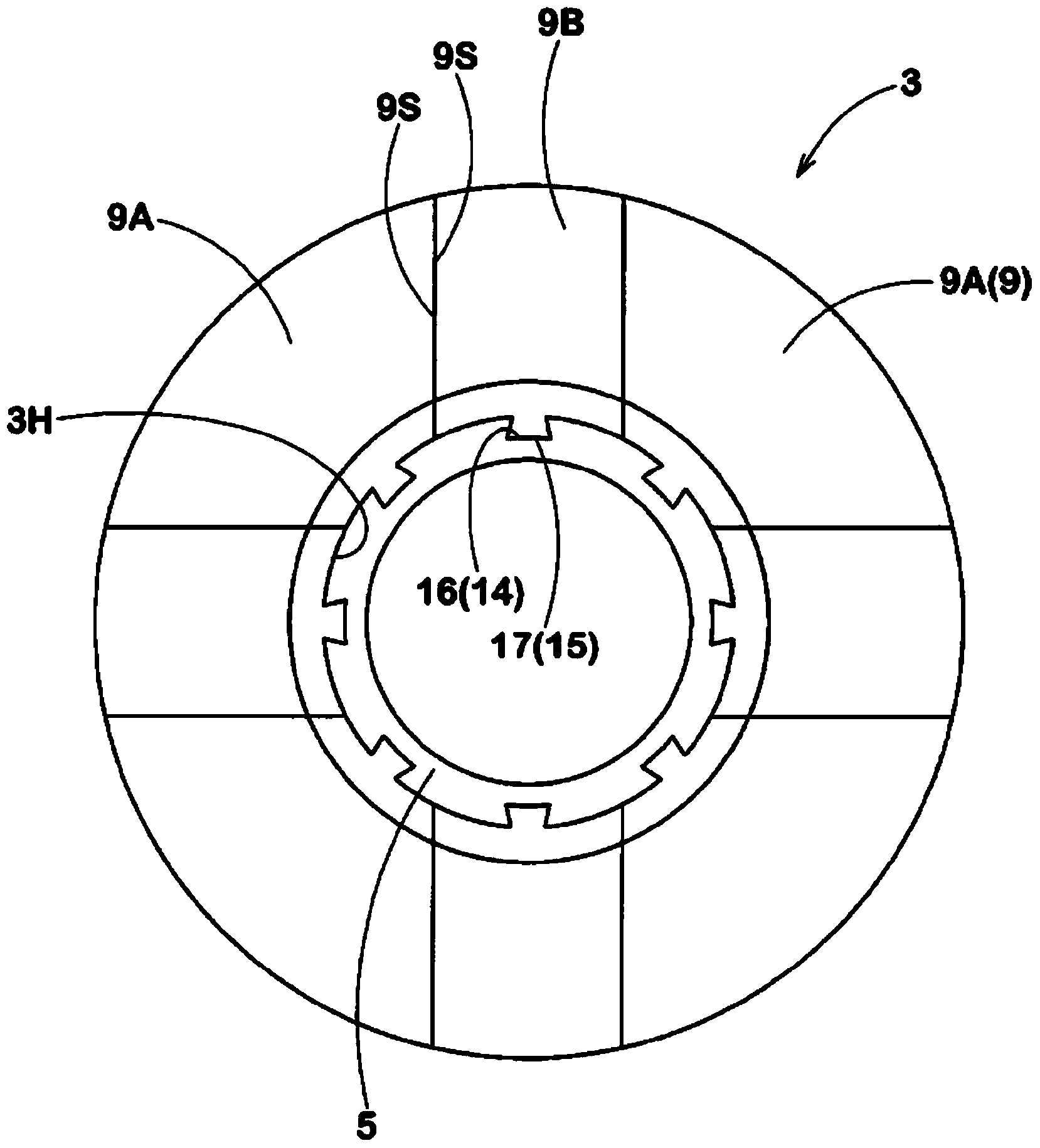
[0062] Such as figure 1 As shown in , the rigid core 1 of this embodiment includes:

[0063] an annular core body 3 provided on an outer surface with a molding surface 2 forming a cavity surface Ts of a pneumatic tire T;

[0064] a cylindrical core 5 inserted into the central hole 3H of the core main body 3; and

[0065] A pair of side plates 6L, 6U are provided on both sides of the core main body 3 along the axis direction.

[0066] In the rigid core 1, tire constituent members such as the inner liner, carcass ply, belt, sidewall rubber, and tread rubber are successively adhered to the molding surface 2 of the rigid core 3 to form an unvulcanized tire. And then, the unvulcanized tire is placed into a vulcanization mold together with the rigid core 1 to be vulcanized. figure 1 A state in which the rigid core 1 is removed from the vulcanization mold and transferred to the holding shaft 4 together...


PUM


Abstract

A rigid core is efficiently, stably and very accurately assembled and disassembled without using a bolt. The rigid core is provided with: a core body (3) comprising a plurality of core segments (9) divided in the circumferential direction of the tire; a cylindrical core (5) for preventing the movement of each core segment (9) toward the inside in the radial direction, and inserted into the center hole of the core body (3); and a pair of side plates (6U, 6L) for preventing the movement of each core segment (9) in the axial direction thereof, by being positioned on both sides in the axial direction of the core body (3), and by sandwiching and holding the core body (3) between the inside surfaces thereof. A first dovetail part (16) is formed on the outer circumferential surface of the core (5), and a second dovetail part (17) for engaging with the first dovetail part (16) is formed on the inner circumferential surface of each core segment (9). The side plate (6U, 6L) on one side is fixed to the end of the core (5) on one side thereof, and the side plate (6U, 6L) on the other side is equipped with a boss part (22) that projects therefrom and can be threaded into an internal thread (13) provided in the central hole of the core (5).

Description

technical field [0001] The present invention relates to a rigid core which is detachable from a pneumatic tire and which can be reinstalled with high precision and high efficiency. Background technique [0002] Recently, such as Figure 10 As shown in (A), in order to improve the forming accuracy of a pneumatic tire, a vulcanization method for a pneumatic tire is proposed (for example, Patent Document 1) by using a rigid core having an outer shape corresponding to the inner surface shape of the tire ( a) to achieve. In this method, tire constituent members such as innerliner, carcass ply, belt, sidewall rubber, and tread rubber are sequentially adhered to a rigid core (a) to form an unvulcanized tire ( t). The unvulcanized tire (t) is put into a vulcanization mold (b) together with a rigid core (a), and is vulcanized between the rigid core (a) as an inner mold and the vulcanization mold (b) as an outer mold. [0003] Such as Figure 10 As shown in (B), the core body (a1) ...

Claims


Application Information

Patent Timeline
IPC IPC(8): B29D30/12B29C33/02B29C35/02B29L30/00
CPCB29D30/0661B29C33/76
Inventor 鬼松博幸
Owner SUMITOMO RUBBER IND LTD