Piston assembly, fluid pressure cylinder, method for manufacturing piston assembly
A technology of assembly and piston, applied in the direction of fluid pressure actuating device, piston, manufacturing tool, etc., can solve the problems such as the inability to obtain sealing performance, and achieve the effects of simplified structure, elimination of reliability and cost reduction
- Summary
- Abstract
- Description
- Claims
- Application Information
AI Technical Summary
Problems solved by technology
Method used
Image
Examples
no. 1 example
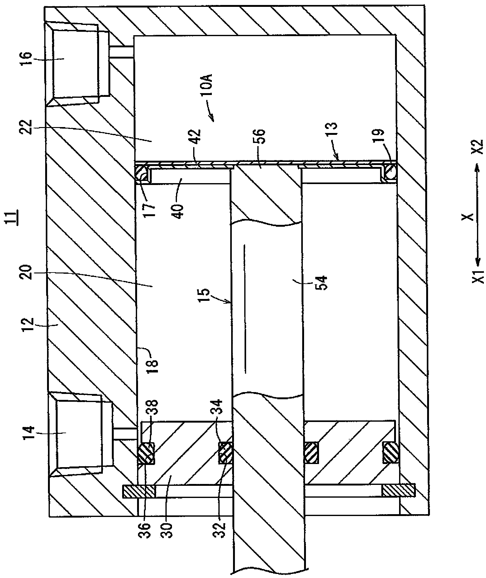
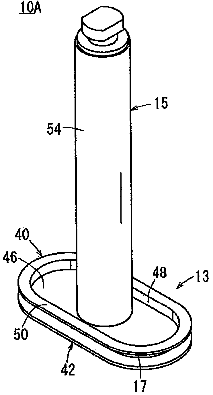
[0048] figure 1 is a partially omitted vertical sectional view along the axial direction of the fluid pressure cylinder 11 equipped with the piston assembly according to the first embodiment of the present invention. The fluid pressure cylinder 11 includes: a casing (cylinder body) 12 as its basic constituent elements, a piston body 13 arranged movably in the axial direction inside the casing 12, and a piston rod 15 connected to the piston Subject 13. Due to the action of the fluid pressure, the piston body 13 moves axially in the housing 12 , so that the piston rod 15 connected to the piston body 13 moves reciprocally.
[0049] The casing 12 is constructed of a metal material such as aluminum alloy or the like, is mounted with a pair of ports 14 , 16 , and has a slide hole (cylinder chamber) 18 inside which communicates with the ports 14 , 16 . In the inside of the slide hole 18, the piston main body 13 can move reciprocally in the axial direction within a certain limited r...
no. 2 example
[0073] Next, refer to Figures 4A to 5 , the piston assembly 10B according to the second embodiment will be explained. In the piston assembly 10B according to the second embodiment, components whose functions and effects are the same as those of the piston assembly 10A according to the first embodiment are denoted by the same symbols and detailed description thereof is omitted.
[0074] The piston assembly 10B according to the second embodiment is equipped with a piston main body 60 whose structure is different from figure 1 and so on the piston body 13 shown. The piston main body 60 is composed of a first piston member 62 and a second piston member 64 .
[0075] Each of the first piston member 62 and the second piston member 64 is an oblong plate-shaped member as a whole, which is formed by plastic deformation (such as press working) of a metal plate, and the first piston member 62 and the second piston member 62 The two piston members 64 are joined to each other by weldin...
no. 3 example
[0084] Next, refer to Figures 6A to 7 , a piston assembly 10C according to the third embodiment will be explained. In the piston assembly 10C according to the third embodiment, components whose functions and effects are the same as those of the piston assembly 10A according to the first embodiment are denoted by the same symbols and detailed description thereof is omitted.
[0085] A piston assembly 10C according to the third embodiment includes a piston main body 80 , and a piston rod 81 connected to the piston main body 80 . Piston rod 81 is configured from figure 1 The piston rod 15 shown etc. omits the fitting portion 56 . and Figure 3C The same weld protrusion 58 shown is provided on the proximal end surface of the piston rod 81 .
[0086] The piston body 80 is composed of a first piston member 82 and a second piston member 42 . The first piston member 82 is configured to Figure 2B The first piston member 40 shown etc. omits the through hole 47 . More specifical...
PUM
 Abstract
Description
Claims
Application Information
 - R&D
- Intellectual Property
- Life Sciences
- Materials
- Tech Scout
- Unparalleled Data Quality
- Higher Quality Content
- 60% Fewer Hallucinations
Browse by: Latest US Patents, China's latest patents, Technical Efficacy Thesaurus, Application Domain, Technology Topic, Popular Technical Reports.
© 2025 PatSnap. All rights reserved.Legal|Privacy policy|Modern Slavery Act Transparency Statement|Sitemap|About US| Contact US: help@patsnap.com


