Vertical shaft stirrer

A mixer and vertical shaft technology, applied in the field of mixing equipment and vertical shaft mixers, can solve the problems that the materials in the tank cannot be fully mixed, the effect of mixing and mixing is affected, and the material utilization is insufficient, so as to achieve high practicability and market competitiveness. Mixing efficiency and mixing uniformity, the effect of low price

Active Publication Date: 2014-03-12
四川宏劲机械有限公司
View PDF7 Cites 7 Cited by
  • Summary
  • Abstract
  • Description
  • Claims
  • Application Information

AI Technical Summary

Problems solved by technology

In the prior art, only the stirring arm for stirring is installed in the stirring tank, and the stirring range of the stirring arm is relatively narrow, and the stirring direction is consistent, that is, the stirring is always rotated clockwise or counterclockwise, so that the materials in the tank cannot be fully mixed In addition, during the mixing operation, a large number of materials tend to accumulate on the tank wall, which not only affects the mixing and mixing effect, but also has a high residual rate of materials in the tank when the material is finally unloaded, and the material is not fully utilized, which increases production costs and causes waste of resources

Method used


Image

  • Vertical shaft stirrer
  • Vertical shaft stirrer
  • Vertical shaft stirrer

Examples


Embodiment 1

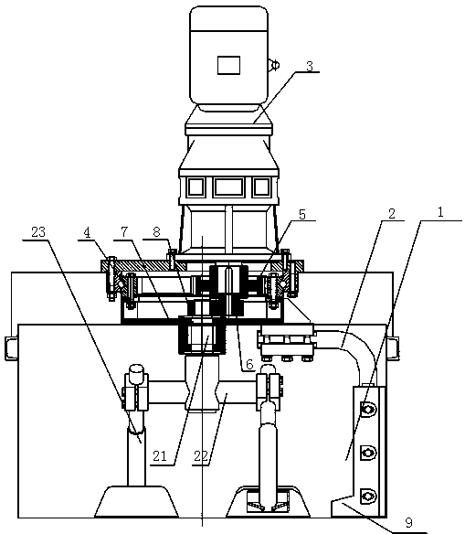
[0030] Such as figure 1 As shown, this embodiment provides a vertical shaft mixer, which mainly overcomes the problems of low mixing efficiency in the prior art, uneven mixing of materials and easy accumulation on the inner wall of the tank. The vertical shaft mixer mainly includes a power mechanism 3, a stirring tank Tank body 1, stirring arm, slewing bearing, scraping arm 2 and other parts.

[0031] Power mechanism, the general power mechanism is composed of a motor and a reducer. On this basis, the output shaft of the power mechanism is the output shaft of the reducer. In addition, the power mechanism can also use other power systems such as geared motors and hydraulic motors. It belongs to the existing mature technology, so this embodiment will not repeat it. The power mechanism has an output shaft, and in this embodiment, a duplex gear is sleeved on the output shaft. The term "dual gear" refers to a gear with two gears superimposed and connected as one structure. For th...

Embodiment 2

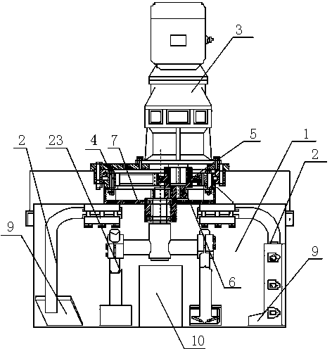
[0042] Such as figure 2 As shown, the differences between this embodiment and Embodiment 1 are: 1. The number of scraping arms is two; The steel pipe is used to prevent materials from accumulating in the central area of ​​the stirring tank body 1 .

Embodiment 3

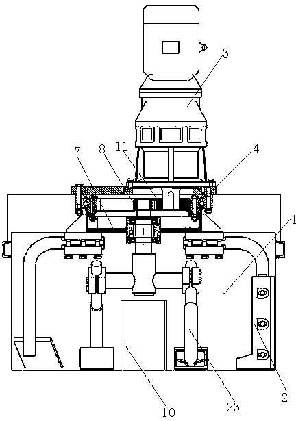
[0044] Such as image 3 , 4 As shown, the difference between this embodiment and Embodiments 1 and 2 is that the gear linkage mechanism includes an output tooth 11 sleeved on the output shaft of the power mechanism 3, and the right end of the output tooth 11 is connected to the inner ring of the inner ring of the slewing bearing 4. Teeth mesh, and its left end meshes with meshing gear 8. On the basis of the above structure, the connecting turntable 7 is in the shape of an inner hollow disc, with an opening at its upper end, and a connecting plate for connecting with the inner ring of the slewing bearing on the edge of the upper end; the connecting shaft of the stirring arm passes through the connecting The turntable extends into the inner ring of the slewing support, and the meshing gear 8 sleeved on the end of the connecting shaft meshes with the output teeth 11 in the inner ring of the slewing support.


PUM


Abstract

The invention discloses a vertical shaft stirrer and mainly solves the problems that an existing stirrer is low in stirring efficiency and poor in effect. The vertical shaft stirrer comprises a stirring tank body, stirring arms, a power mechanism, slewing bearings and a connection rotation disc, wherein the connection rotation disc and inner rings in the slewing bearings are fixedly connected and keep synchronous movement; an integrated duplicate gear formed by connecting a first gear and a second gear in an overlapping mode is arranged on an output shaft of the power mechanism in a sleeved manner; the first gear and inner teeth of the inner rings in the slewing bearings are meshed; a through hole is formed in the center of the connection rotation disc; a connection shaft of the stirring arms passes through the through hole, and one end part of the connection shaft is sleeved with a meshing gear which is meshed with the second gear and is coaxial with the slewing bearings; scraping arms are in fastening connection with the connection rotation disc, keep the synchronous movement, are placed inside the stirring tank body and are used for scraping accumulation materials on tank wall, and are arranged on the connection rotation disc. According to the positive and negative combination movement of the stirring arms and the scraping arms, the materials can be adequately stirred and the stirring effect is relatively good.

Description

technical field [0001] The invention belongs to the technical field of machinery and relates to a stirring device, in particular to a vertical shaft stirrer. Background technique [0002] In the concrete preparation process, the mixing tank is a commonly used mechanical equipment for mixing concrete. In the prior art, only the stirring arm for stirring is installed in the stirring tank, and the stirring range of the stirring arm is relatively narrow, and the stirring direction is consistent, that is, the stirring is always rotated clockwise or counterclockwise, so that the materials in the tank cannot be fully mixed In addition, during the mixing operation, a large amount of materials tend to accumulate on the tank wall, which not only affects the mixing and mixing effect, but also has a high residual rate of materials in the tank when the materials are finally unloaded, resulting in insufficient material utilization, which increases production costs and causes waste of reso...

Claims


Application Information

Patent Timeline
Patent Type & Authority Applications(China)
IPC IPC(8): B28C5/16
CPCB28C5/0831B28C5/16
Inventor 薛辉税小明吴德勇
Owner 四川宏劲机械有限公司
Why Eureka
Try Eureka