Pre-detecting method and controlling method for pressure refueling

A pre-detection and pressure technology, applied in the field of machinery, can solve the problems of reduced safety, lack of pre-detection control function, no pre-detection control, etc., to achieve the effect of ensuring safety

Inactive Publication Date: 2014-03-12
HARBIN
5 Cites 9 Cited by

AI-Extracted Technical Summary

Problems solved by technology

Due to the relatively backward aviation technology in our country, there are few models independently developed in my country, and the technical level is relatively backward. Only a small number of models are equipped with pressure refueling systems. The control method of the system is still an early control technology, and there is no pre-detection control. function, it is not easy to be found when the system fails
Although the refueling speed of the pressure refueling system is fast, the risk of pressure refueling is relatively hi...

Method used

What the fuel tank box body in the ground test structure of pressure refueling system adopts is the processing mode of aluminum alloy plate welding forming, and the shape of fuel tank is barrel-shaped, and the reinforced dividing plate of fuel tank inner wall and stamping adopts the welding mode of spot welding Welded together, there are reinforcing grooves and lightening holes on the reinforced partition, and there are grooves on the upper and bottom of the fuel tank for ventilation and oil flow, which enhances the connectivity inside the fuel tank. The fuel tank can withstand 0.02Mpa pressure gas secret test. There are installation holes on the side wall of the fuel tank for installing the oil level signal, overflow valve, and vent float valve. There is a maintenance port cover on the end cover, and ...

Abstract

The invention relates to the field of machines, and provides a pre-detecting method and controlling method for pressure refueling. The controlling method comprises the steps that a refueling control switch is placed at the opening position, a fuel oil electric switch is powered on, and at the moment, a refueling indicator light is turned on, and an oil full indicator light is turned off; when the quantity of oil in an oil tank reaches the designed maximum oil charging quantity, an oil level full annunciator sends a signal for cutting off an oil adding pipeline to the fuel oil electric switch, and when the oil adding pipeline is cut off, the oil full indicator light is turned on; if the oil adding pipeline is not cut off through the signal for cutting off the oil adding pipeline, the oil level in the oil tank will continue to rise to reach the warning oil level, a warning oil level annunciator sends a signal for cutting the oil adding pipeline again to the fuel oil electric switch, the oil adding pipeline is cut off, and meanwhile a warning light on a control board is turned on to remind that an oil adding system has a fault. The pre-detecting method and controlling method can detect whether the functions of the indicator lights and the control switch of the system are normal or not before airplane pressure refueling, the risks of airplane tests can be reduced, and the success rate of the airplane tests is improved.

Application Domain

Liquid handling installationsMachines/engines +2

Technology Topic

AirplaneFuel oil +3

Image

  • Pre-detecting method and controlling method for pressure refueling
  • Pre-detecting method and controlling method for pressure refueling

Examples

  • Experimental program(1)

Example Embodiment

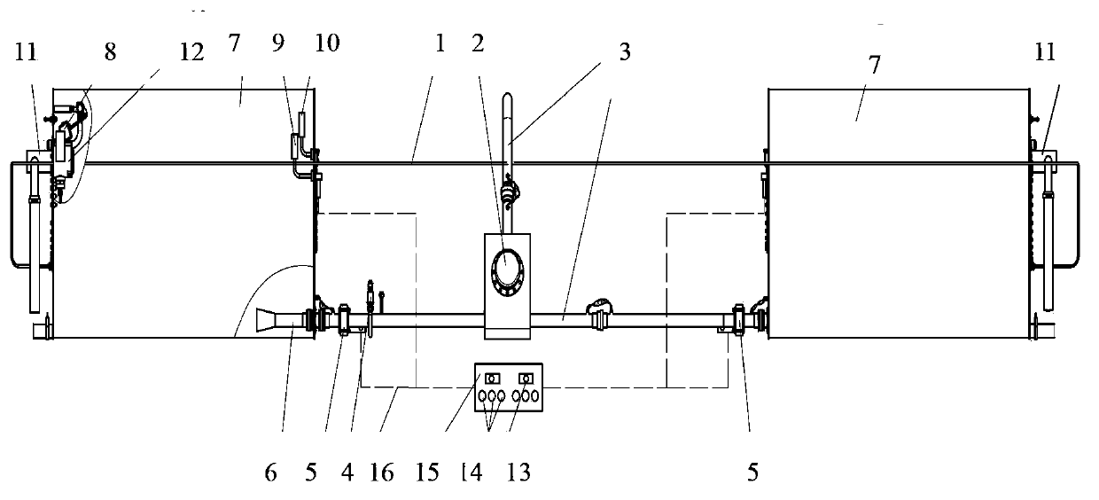
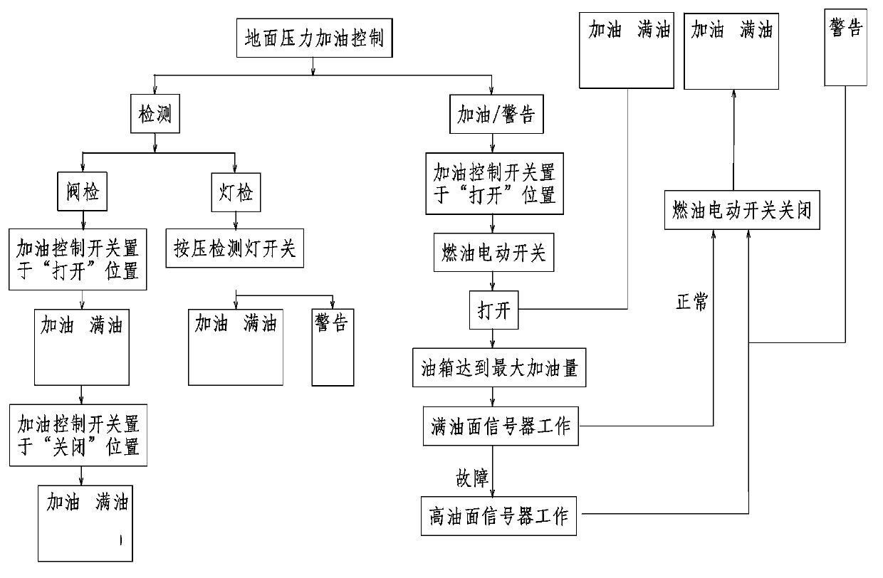
[0021] Combine below figure 1 , figure 2 To illustrate the working of the present invention:
[0022] The pre-detection method and control method of pressure refueling is a design method in which the theoretical design of the on-board pressure refueling system is pre-simulated on the ground. The length and volume of the fuel tank are different from the design on the aircraft. Through the ground test, it is possible to test whether the actual function of the pressure fueling system meets the design requirements.
[0023] The ground test structure of the pressure refueling system matched with the pre-detection method and the control method of the pressure refueling of the present invention is as follows: figure 1 As shown, it mainly includes a set of control pipeline 1, a refueling joint 2, a set of refueling pipeline 3, a vacuum valve 4, two fuel electric switches 5, two nozzles 6, two metal fuel tanks 7, two Float valve 8, two full oil level indicators 9, two warning oil level indicators 10, two overflow pipes 11, two relief valves 12, two fueling control switches 13, six indicator lights 14, one Control box 15 and electrical connection wires 16 .
[0024] When setting, first install the nozzle 6, the float valve 8, the full oil level signal 9, the warning oil level signal 10, the overflow pipe 11, and the overflow valve 12 to the fuel tank, and then install the fueling connector 2 on the bracket, And use the quick-release clamp to connect the outlet end of the refueling connector 2 with the refueling pipeline 3, install the fuel electric switch 5 on the refueling pipeline 3, install the vacuum valve 4 on the manifold, and connect the assembled refueling connector 2, refueling The pipeline 3, the control pipeline 1, the fuel electric switch 5 and the two metal fuel tanks are connected with quick-release clamps, and the control pipeline 1 is connected between the metal fuel tank 7 and the refueling joint 2, and the system assembled according to the above requirements After the electrical system is connected, the ground simulation test can be carried out.
[0025] The fuel tank body in the ground test structure of the pressure refueling system adopts the processing method of welding and forming aluminum alloy plates. The shape of the fuel tank is a barrel shape. , There are reinforcing grooves and lightening holes on the reinforced partition, and grooves are opened on the upper and bottom of the fuel tank for ventilation and oil stringing, which enhances the connectivity inside the fuel tank. The fuel tank can withstand 0.02Mpa pressure air tightness test. There are mounting holes on the side wall of the fuel tank for installing the oil level signal, overflow valve, and ventilation float valve. , The function of the maintenance cover is to install the ventilation float valve, overflow device and control pipeline; the refueling pipeline is made of aluminum alloy conduit, and the connecting part of the conduit adopts the form of quick-release semi-snap ring connection, which is very easy to install and disassemble. It is convenient; the control pipeline is made of metal aluminum alloy conduit, and the conduit is connected by screw connection, and the control conduit is connected with the refueling joint; the vacuum valve is installed on the refueling pipeline to ventilate the refueling pipeline when the oil is pumped by pressure; The refueling control box is connected with the oil level annunciator and the electric fuel switch.
[0026] like figure 2 As shown, during the test, the pre-test of pressure refueling is firstly carried out, including:
[0027] S101. Press the detection switch, and the refueling indicator, full oil indicator, and warning indicator all turn from off to on.
[0028] S102. Set the fueling control switch to the ON position, the fueling indicator light turns from off to on, and the full fuel indicator turns from on to off.
[0029] S103. Set the fueling control switch to the off position, the fueling indicator light turns from on to off, and the full fuel indicator turns from off to on.
[0030] After the pre-test of pressure refueling, carry out the control test of pressure refueling, including:
[0031] S201. Put the refueling control switch to the ON position, and the electric fuel switch is turned on. At this time, the refueling indicator light turns from off to on, and the full fuel indicator turns from on to off.
[0032] S202. When the fuel volume in the fuel tank reaches the designed maximum fuel volume, the full fuel level signal device sends a signal to the fuel electric switch to cut off the fueling pipeline, and the fueling pipeline is cut off. At this time, the full fuel indicator turns from off to on.
[0033] S203. If the signal for cutting off the fueling pipeline fails to cut off the fueling pipeline, the oil level in the fuel tank continues to rise and reaches the warning oil level, and the warning oil level signal device gives a signal to cut off the fuel electric switch again, and cuts off the fueling pipeline, At the same time, the warning light on the control panel lights up to remind the fuel system failure.
[0034] The pre-detection control method of pressure refueling has been applied for the first time on a new domestic civil aircraft. On the ground test structure of the pressure refueling system, the pre-detection control method of pressure refueling is used to test the light inspection and valve inspection. Press the light After checking the button, all the indicator lights will turn from off to on, and they will automatically rebound when released, and the indicator lights will turn from on to off, and the light inspection function is normal; when the valve is inspected, pull the valve inspection switch, and when the switch is in the refueling position, the refueling indicator light When the switch is in the off position, the full oil indicator light is on, and the valve inspection function is normal. After the lamp inspection and valve inspection test, the refueling control test was carried out. First, the refueling pipe on the refueling vehicle was docked with the refueling connector in the ground test structure. The fuel electric switch was turned off, and the fuel did not enter the fuel tank. Turn on, the refueling indicator light is on, the fuel tank is in refueling state, when the oil level reaches the working position of the full oil level indicator, the fuel electric switch cuts off the refueling pipeline, the refueling stops, the refueling indicator light is off, and the full oil indicator light is on; continue to refuel the fuel tank , When the working position of the warning oil level signal is reached, the fuel electric switch cuts off the refueling pipeline again, and the full oil level and the warning oil level indicator light are on at the same time, indicating that the oil level in the fuel tank reaches the working state of the warning oil level at this time. , to warn the staff that the oil in the fuel tank has reached the warning oil level and must stop refueling immediately. After the refueling test, the system conducts an overflow test when the fuel tank is full, keeping the electric fuel switch on all the time to continuously refuel the fuel tank, the fuel tank is full of fuel, the float valve is closed, and the fuel overflows from the overflow valve. The pressure of the middle fuel tank is always lower than the design pressure value of the fuel tank by 0.02Mpa. The test results show that the design can detect the function of the system in advance before pressure refueling, can ensure the normal function during pressure refueling, realize the automatic control of the refueling process, and ensure the safety of the aircraft, and the effect is very good.

PUM

no PUM

Description & Claims & Application Information

We can also present the details of the Description, Claims and Application information to help users get a comprehensive understanding of the technical details of the patent, such as background art, summary of invention, brief description of drawings, description of embodiments, and other original content. On the other hand, users can also determine the specific scope of protection of the technology through the list of claims; as well as understand the changes in the life cycle of the technology with the presentation of the patent timeline. Login to view more.

Similar technology patents

Classification and recommendation of technical efficacy words

Why Eureka
Try Eureka