Flat knitting machine with lighting device

A technology for flat knitting machines and lighting devices, which is applied to knitting, flat knitting machines with single-action needles, weft knitting, etc., which can solve the problems of inconvenient fault finding and inability to illuminate the working space of the slider

Active Publication Date: 2014-03-12
KARL MAYER STOLL R&D GMBH
View PDF5 Cites 6 Cited by
  • Summary
  • Abstract
  • Description
  • Claims
  • Application Information

AI Technical Summary

Problems solved by technology

[0003] However, the lighting arranged above the carriage cannot illuminate the working space below the carriage, since parts of the carriage and other components (such as thread guides) are arranged between the li...

Method used


Image

  • Flat knitting machine with lighting device
  • Flat knitting machine with lighting device
  • Flat knitting machine with lighting device

Examples


Embodiment Construction

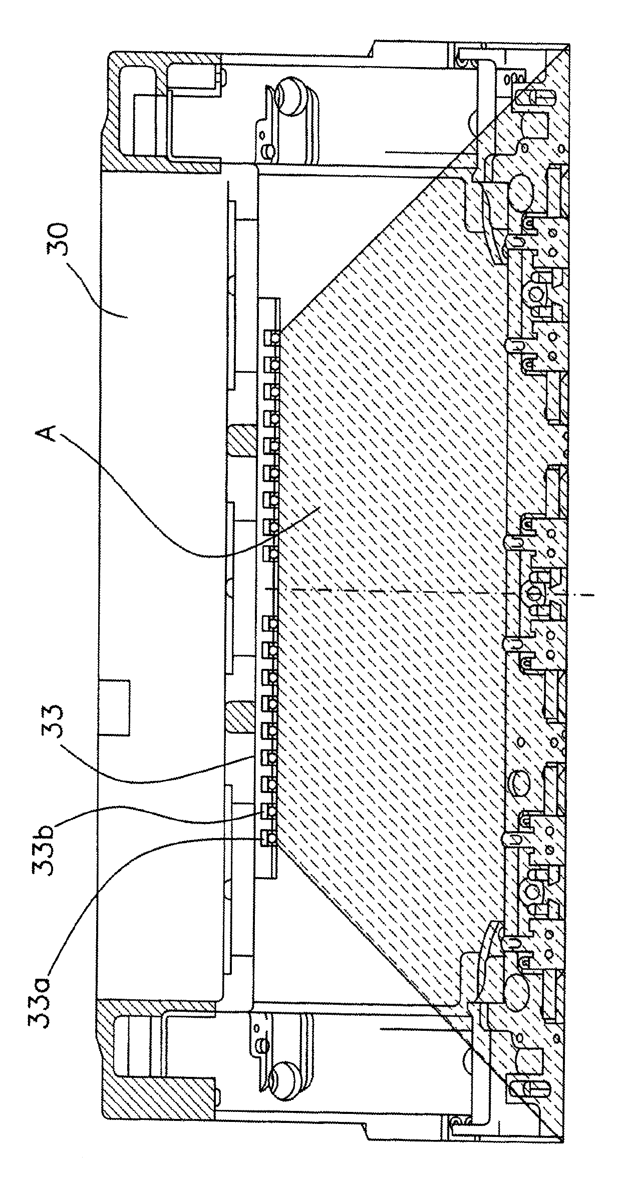
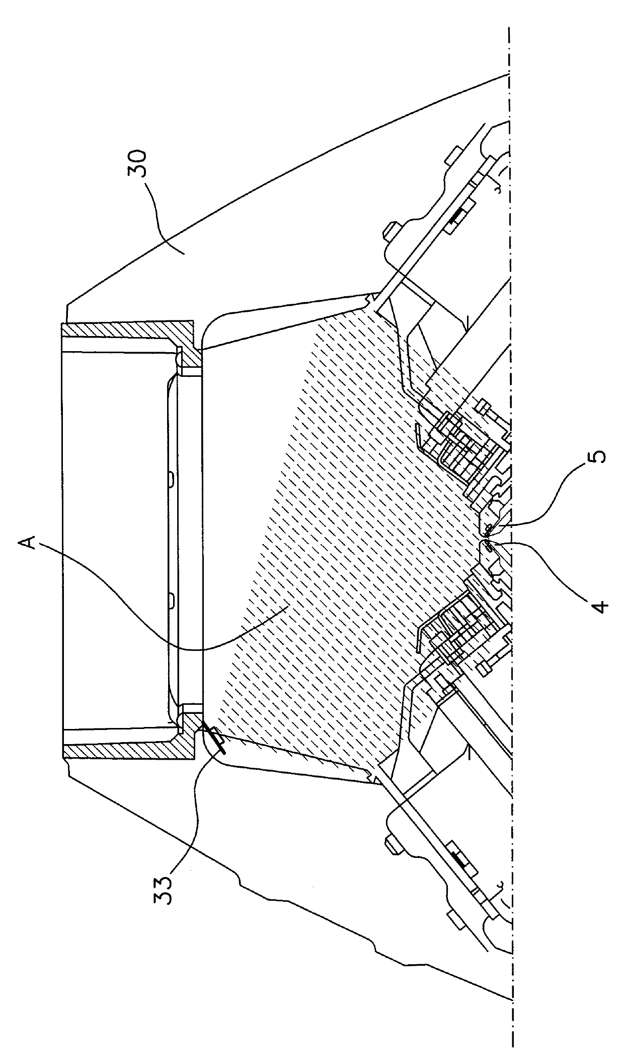
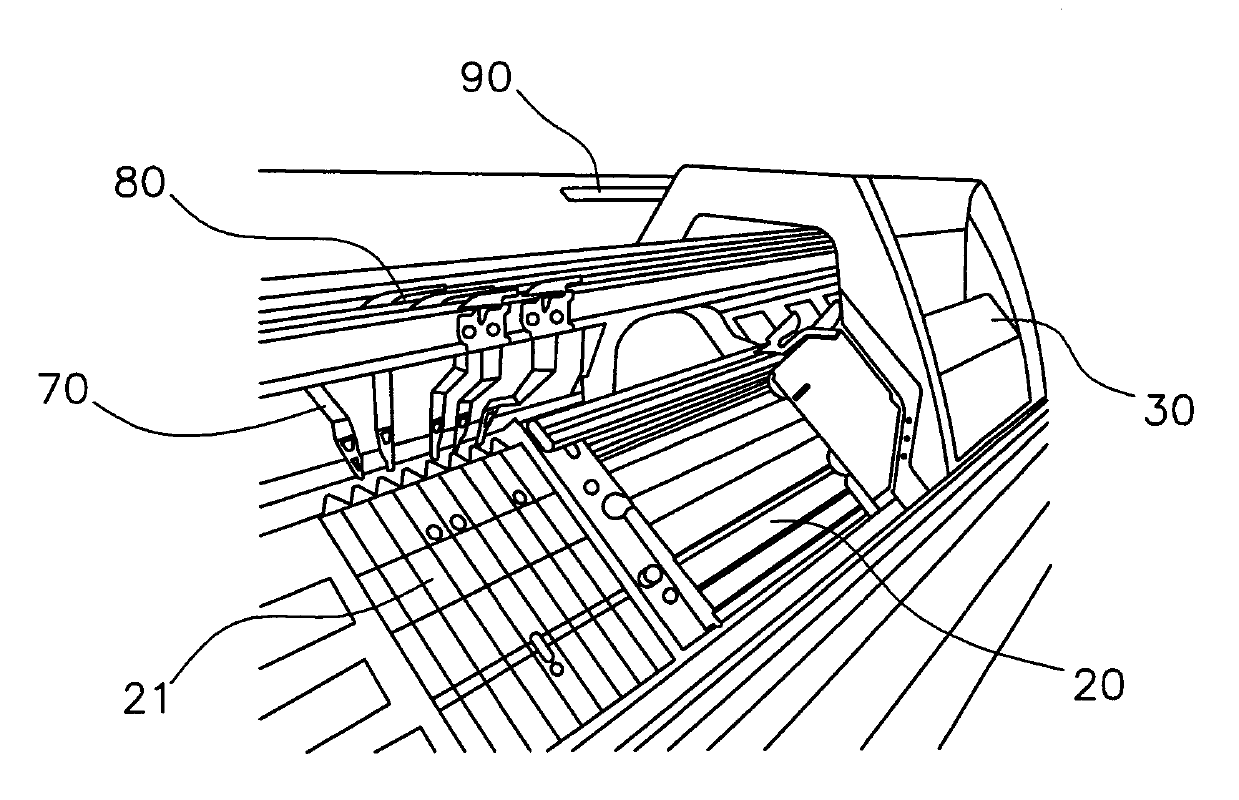
[0017] Figure 1a A flat knitting machine 100 is shown with a frame 10 and front and rear needle beds 20 . Introduced in the needle bed 20 are guide grooves for knitting elements such as needles or sliders. The knitting elements can be moved longitudinally in their guide grooves by means of a cam (not visible here) mounted on the machine carriage 30 . Furthermore, the machine carriage 30 is moved back and forth along the needle bed 20 . The thread 41 required for producing the knitted fabric extends from the yarn bobbin 40 through the yarn control unit 50 and the yarn feeder (Fournisseur) to the yarn guide 70 (which is also passed through a slide over the needle bed 20 after corresponding selection). seat 30 to move it and thus supply the selected needle with thread 41). Here, the thread guide 70 slides on a thread guide rod 80 which extends in its longitudinal direction above the needle bed 20 .

[0018] Such as Figure 1a As shown, an illumination device 90 is arranged ab...


PUM


Abstract

The machine has machine carriages (30) moved over rear and front needle beds (4, 5) for controlling needle movements. An illumination device (33) is adjustably arranged at the carriages for illuminating a knitting chamber below the carriages. The illumination device is switched manually and/or by a machine controller and/or a knitting program. The illumination device comprises sealing strips. The illumination device is arranged at the carriages over the rear and front needle beds. The illumination device is provided with LEDs as lights.

Description

technical field [0001] The invention relates to a flat knitting machine with an illuminating device. Background technique [0002] Modern flat knitting machines (Flachstrickmaschnie) are equipped with lighting in the area above the carriage (Schlitten) for illuminating the working space of the machine, as well as in the area of ​​the knit trough (Gestrickwanne) for the finished knitted pieces Equipped with lighting. [0003] However, the lighting arranged above the carriage cannot illuminate the working space below the carriage, since parts of the carriage and other components (for example thread guides) are arranged between the lighting and the working space. This is especially inconvenient when fault-finding if the carriage stops above the fault position due to a yarn break or a break in the needle butt (Nadelfu™) or slider butt (Platinenfu™). The shadows cast by the carriage and other components onto the needle space below necessitate the consideration of additional ext...

Claims


Application Information

Patent Timeline
IPC IPC(8): D04B15/32
CPCD04B7/00
Inventor M.布克R.黑内斯
Owner KARL MAYER STOLL R&D GMBH
Why Eureka
Try Eureka