
Method and sensor arrangement for detecting the visibility outside of a motor vehicle

A technology for sensor devices and motor vehicles, which is applied in the direction of measuring devices, signaling devices, lighting devices, etc., and can solve problems such as inability to detect effectively and poor field of vision

Active Publication Date: 2015-07-08
HELLA KG HUECK & CO
View PDF8 Cites 0 Cited by
  • Summary
  • Abstract
  • Description
  • Claims
  • Application Information

AI Technical Summary

Problems solved by technology

However, with the known sensor devices it may not be possible to detect very effectively the reduced visibility not only during the day but also at night, for example due to fogging
The changed visibility situation is thus only detected by the motor vehicle driver, who often takes appropriate measures, such as reducing the speed of the vehicle, to avoid a potentially dangerous situation already too late

Method used


Image

  • Method and sensor arrangement for detecting the visibility outside of a motor vehicle
  • Method and sensor arrangement for detecting the visibility outside of a motor vehicle
  • Method and sensor arrangement for detecting the visibility outside of a motor vehicle

Examples


Embodiment Construction

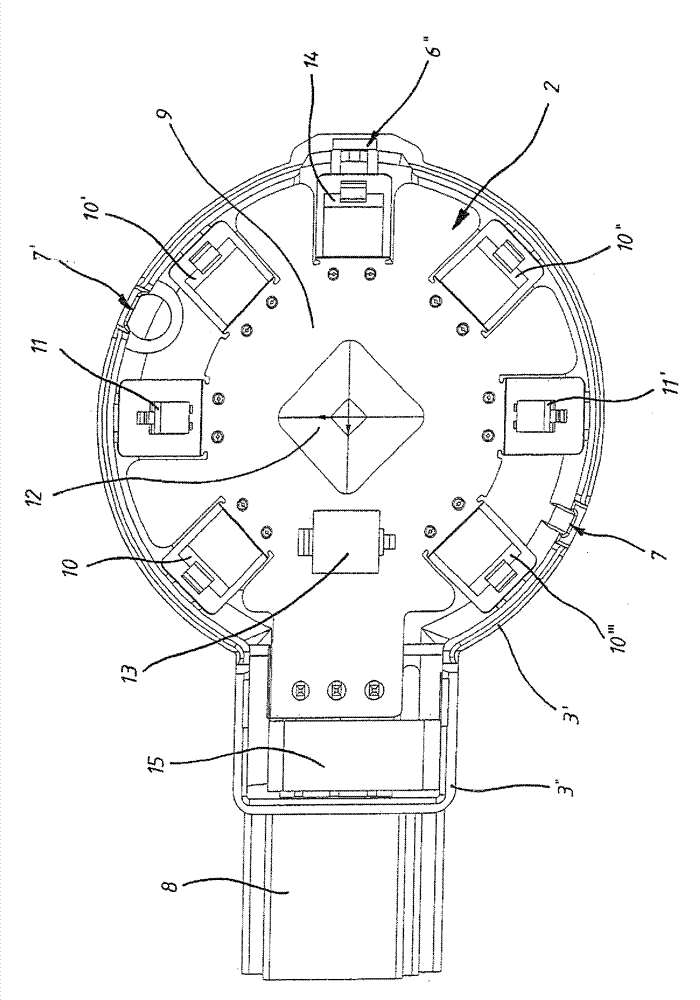
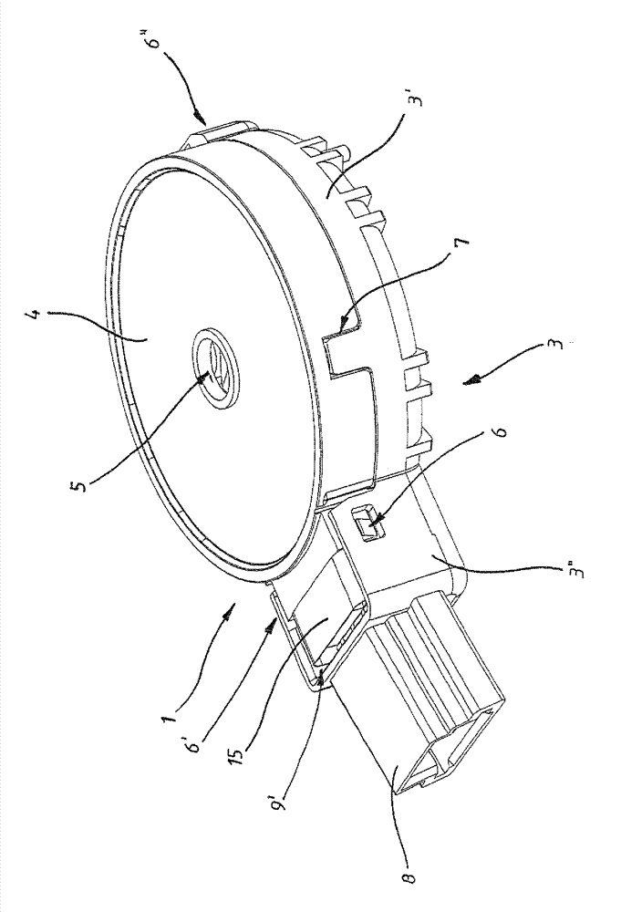
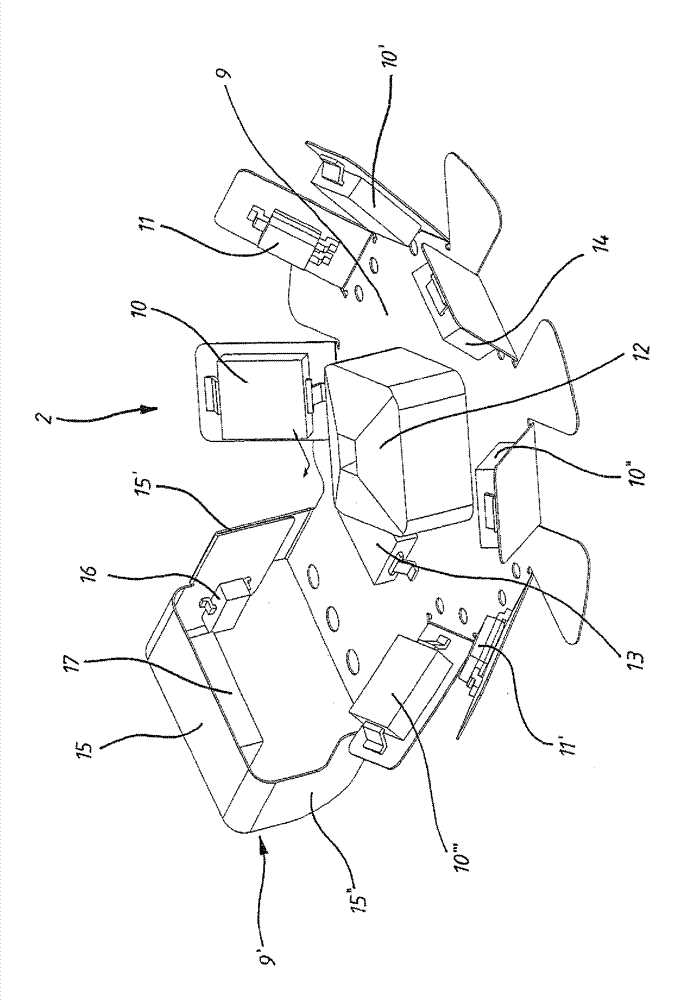
[0024] Denote the housing of the sensor device 2 with 1 ( figure 2 ). This housing 1 has a receptacle 3 and a cover 4 which are releasably connected to one another. The cover plate 4 is substantially circular and has a perforation 5 in the central region of the formed circle. The receiving part 3 has a circular first receiving area 3' and an elongated second connecting area 3''. For connecting the receiving part 3 and the cover plate 4, three detent connections 6, 6', 6'' and two plug connections 7, 7' are provided. The receiving part 3 has three stop elements of the stop connection 6 , 6 ′, 6 ″, in which two stop elements of the stop connection 6 , 6 ′ Elements are arranged on the elongated connection region 3 ″ at the first end of the connection region 3 ″ which rests on the receiving region 3 ′, and the third stop of the locking connection 6 ″ The moving element is arranged on the circular receiving area 3 ′ on the side opposite the elongated connecting area 3 ″. Furt...


PUM


Abstract

The invention relates to a method for detecting the visibility outside of a motor vehicle by means of at least two light sensors, in the case of which the intensity of the light reflection of the driving light emitted in the direction of travel is detected by means of a first light sensor, which is oriented in the direction of travel. The first light sensor thereby transmits at least a first evaluation signal to a control unit for further processing at least as a function of the recorded intensity of the light reflection. The ambient light is detected by means of a second light sensor and a second evaluation signal is transmitted to the control unit as a function of the intensity of the ambient light. The control unit correlates the evaluation signals of both light sensors and the light intensity threshold value is determined on the basis thereof. The control unit outputs different control signals in each case, in response the first evaluation signal is exceeding of falling below of the determined light intensity threshold value.

Description

technical field [0001] The invention relates to a method for detecting visibility outside a motor vehicle by means of at least two light sensors. Furthermore, the invention also relates to a sensor device for detecting a field of view for a motor vehicle, which sensor device has at least one light sensor which can be arranged in an orientation in the direction of travel. Background technique [0002] Known methods and sensor devices are used to detect the visibility situation during driving, in particular outside the motor vehicle, and to switch on the driving lights if necessary. For example, when the motor vehicle enters a long dark road or enters a tunnel and then activates the headlights, since the existing light conditions and thus the visibility are not sufficient for the driver to control the vehicle without risk. Motor vehicles make it through the tunnel. [0003] For example, DE 196 30 216 C2 discloses a sensor device of the type mentioned at the beginning, which ...

Claims


Application Information

Patent Timeline
Patent Type & Authority Patents(China)
IPC IPC(8): B60Q1/00B60Q1/04B60Q1/20B60Q1/30H05B37/02
CPCG01D21/02B60Q1/00B60Q1/02B60R1/00B60R21/00G08G1/0965G08G1/0968G08G1/16
Inventor T.尼曼O.吕特克A.施拉尔曼J.帕洛克斯A.米勒T.佩塔施
Owner HELLA KG HUECK & CO
Learn More