

Solar cooling system
A technology of solar refrigeration and solar heat collector, applied in the field of solar energy utilization
- Summary
- Abstract
- Description
- Claims
- Application Information
AI Technical Summary
Problems solved by technology
Method used
Image

Examples
Embodiment 1
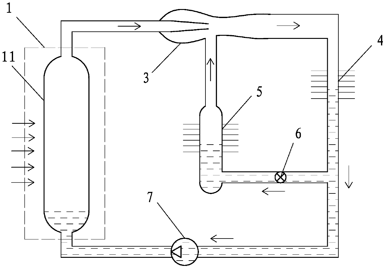
[0060] like figure 1 The solar refrigeration system shown includes a solar heat collector 1, a jet pump 3, a heat exhauster 4 and a heat absorber 5, and the pressure bearing capacity of the heated fluid passage 11 of the solar heat collector 1 is greater than 0.15MPa, and the The heated fluid passage 11 is set as a fluid vaporization passage, and the gas outlet of the fluid vaporization passage communicates with the power fluid inlet of the jet pump 3 , and the low-pressure gas inlet of the jet pump 3 communicates with the gas outlet of the heat absorber 5 , the gas outlet of the jet pump 3 communicates with the gas inlet of the heat extractor 4, the liquid outlet of the heat extractor 4 communicates with the liquid inlet of the heat absorber 5 through a throttling control valve 6, and the The liquid outlet of the heat extractor 4 communicates with the liquid inlet of the fluid vaporization channel through a liquid pump 7 .
Embodiment 2
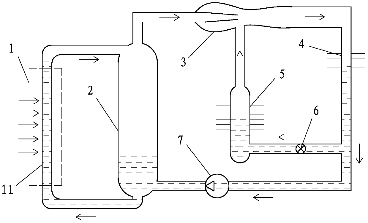
[0062] like figure 2 The solar refrigeration system shown includes a solar heat collector 1, a jet pump 3, a heat exhauster 4 and a heat absorber 5, and the pressure bearing capacity of the heated fluid passage 11 of the solar heat collector 1 is greater than 0.15MPa, and the The fluid inlet of the heated fluid channel 11 communicates with the liquid outlet of the gas-liquid separator 2, the fluid outlet of the heated fluid channel 11 communicates with the gas-liquid mixture inlet of the gas-liquid separator 2, and the gas-liquid separator 2 The gas outlet communicates with the power fluid inlet of the jet pump 3, the low-pressure gas inlet of the jet pump 3 communicates with the gas outlet of the heat absorber 5, and the gas outlet of the jet pump 3 communicates with the heat exhauster 4 The gas inlet of the heat extractor 4 is communicated with the liquid outlet of the heat absorber 5 through the throttling control valve 6, and the liquid outlet of the heat extractor 4 is c...
Embodiment 3
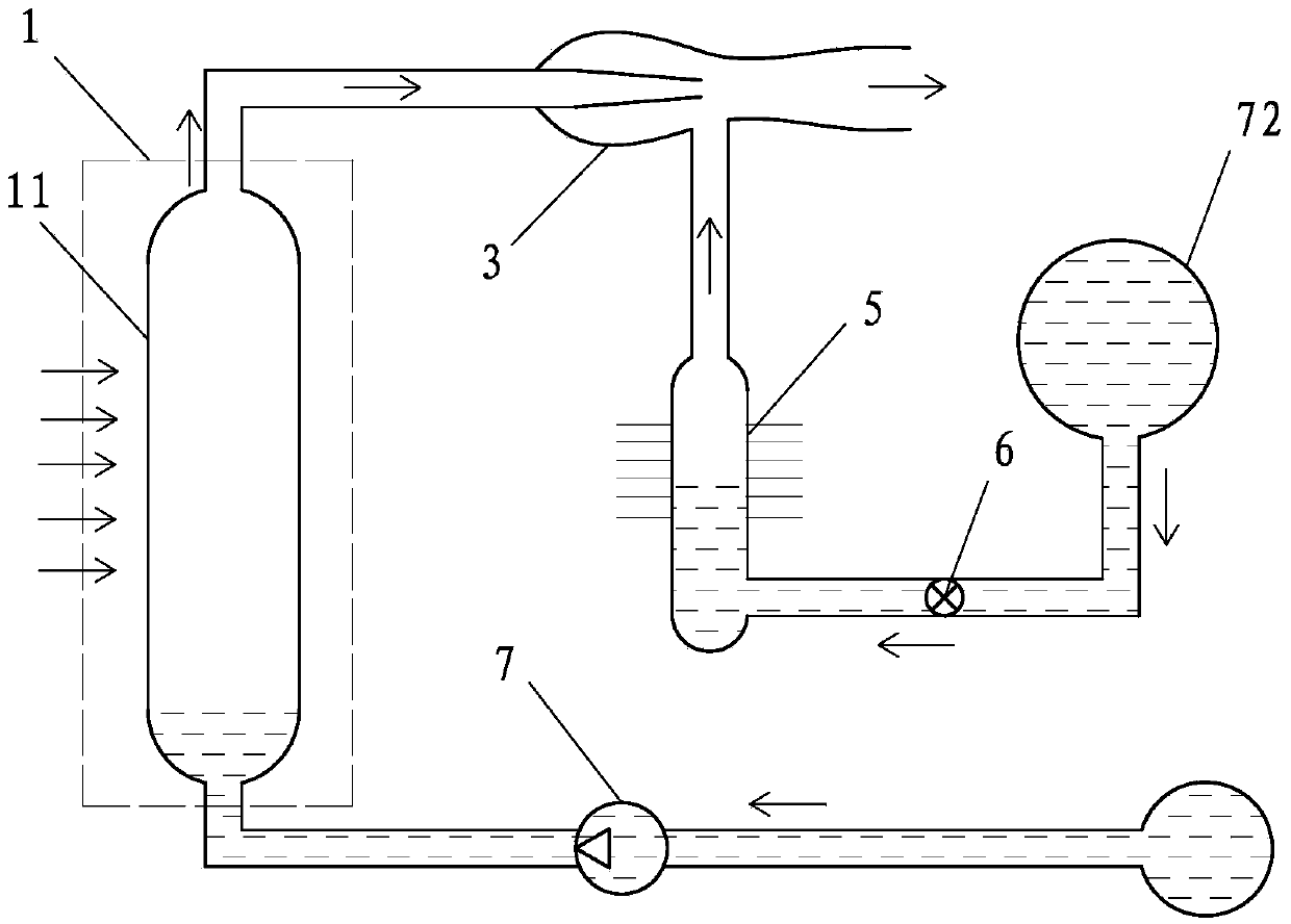
[0065] like image 3 The solar cooling system shown includes a solar heat collector 1, a jet pump 3 and a heat absorber 5, the pressure bearing capacity of the heated fluid passage 11 of the solar heat collector 1 is greater than 0.15MPa, and the heated fluid passage 11 is set It is a fluid vaporization channel, the gas outlet of the fluid vaporization channel communicates with the power fluid inlet of the jet pump 3, the low-pressure gas inlet of the jet pump 3 communicates with the gas outlet of the heat absorber 5, and the fluid vaporization The liquid inlet of the channel communicates with the liquid outlet of the liquid pump 7 , the liquid inlet of the liquid pump 7 communicates with the liquid source, and the liquid inlet of the heat absorber 5 communicates with the cryogenic liquid source 72 through the throttling control valve 6 .
[0066] As a changeable embodiment, optionally, the cryogenic liquid source 72 and the liquid source are changed to the same cryogenic liqu...
PUM
| Property | Measurement | Unit |
|---|---|---|
| Pressure endurance | aaaaa | aaaaa |
Abstract
Description
Claims
Application Information