Refrigerator

A technology for refrigerators and cold air passages, applied in the field of refrigerators, which can solve the problems of overcooling and freezing of food that is not frozen in water, and achieve the effect of improving preservation and energy saving

Active Publication Date: 2014-03-12
HITACHI APPLIANCES INC
View PDF7 Cites 20 Cited by
  • Summary
  • Abstract
  • Description
  • Claims
  • Application Information

AI Technical Summary

Problems solved by technology

However, the freezing of the water in the ice-making water tank arranged at the lower part of the refrigerator compartment, the overcooling of the food in the small item housing, and the freezing of the food are not considered.

Method used


Image

  • Refrigerator
  • Refrigerator
  • Refrigerator

Examples


no. 1 approach

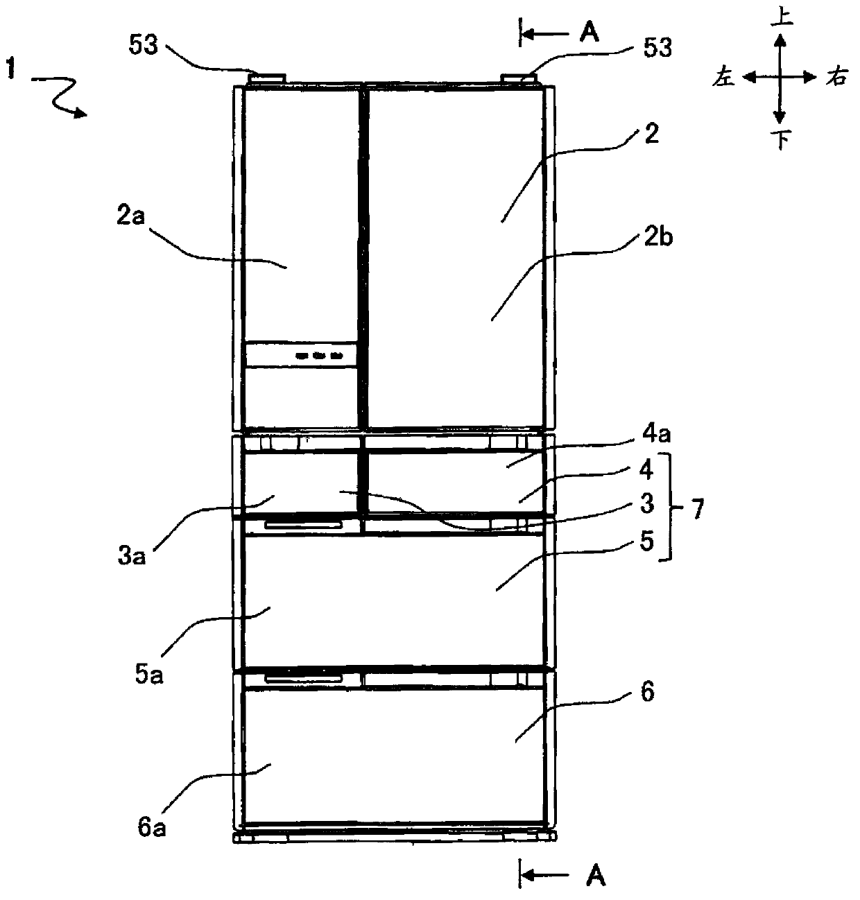
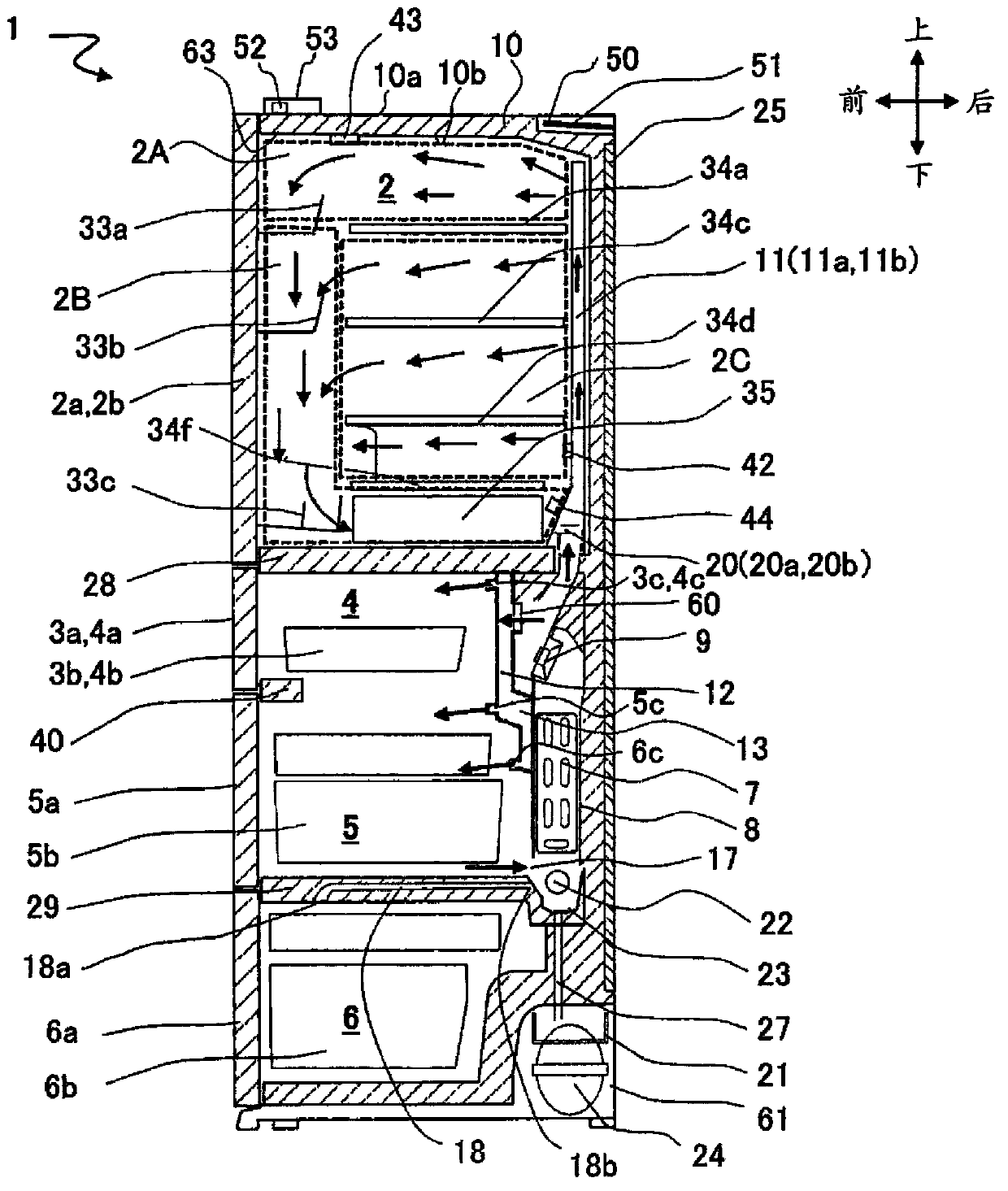
[0038] figure 1 It is a front view of the refrigerator which concerns on 1st Embodiment of this invention. Such as figure 1 As shown, the refrigerator 1 of this embodiment is comprised from the upper side by the refrigerator compartment 2 (store room in a refrigeration temperature range), the freezer compartment 7, and the vegetable compartment 6. Freezer compartment 7 includes lower freezer compartment 5 , ice making compartment 3 and upper freezer compartment 4 arranged side by side above lower freezer compartment 5 .

[0039]Refrigerator compartment 2 is provided with left and right partitioned refrigerator compartment doors 2a, 2b. Ice-making compartment 3, upper freezer compartment 4, lower freezer compartment 5, and vegetable compartment 6 are provided with drawer-type ice-maker door 3a, upper freezer compartment door 4a, and lower compartment door 4a, respectively. Freezer door 5a, vegetable door 6a. Hereinafter, the refrigerating compartment doors 2a, 2b, the ice ma...

Embodiment approach 2

[0094] Then refer to Figure 13a to Figure 15 An example in which the first temperature sensor 44 is installed in another installation location will be described. In addition, about the same structure as Embodiment 1, the same code|symbol is attached|subjected, and description is abbreviate|omitted.

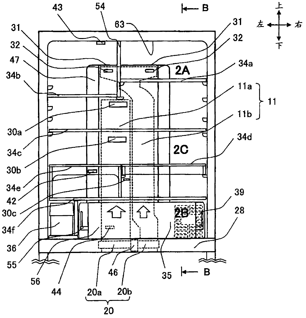
[0095] Figure 13a It is a flow pattern diagram of cool air in the case of cooling through both the first cool air passage 11a and the second cool air passage 11b. Such as Figure 8a , 8b As shown in , 8c, not only is there no food placed on the shelves 34c, 34d in the middle layer, even if food is placed, the flow of cold air discharged from the discharge ports 30a, 30b, 30c of the first cold air passage 11a is also smooth. Next, the foods placed on the shelves 34c, 34d are effectively cooled. However, if Figure 13a As shown, when many foods are placed on the shelves 34c, 34d, the flow of cold air discharged from the discharge ports 30a, 30b deteriorates, and the foods ca...

Embodiment approach 3

[0103] Then refer to Figure 16 , 17 Embodiment 3 will be described. In addition, about the same structure as Embodiment 1, the same code|symbol is attached|subjected, and description is abbreviate|omitted.

[0104] Figure 16 It is a figure explaining the 3rd temperature sensor 42 provided in the refrigerator compartment which concerns on 3rd Embodiment of this invention. The amount of cold air ventilated in the first cold air channel 11a and the second cold air channel 11b is controlled using the third temperature sensor 42 and the second temperature sensor 43 based on the temperatures detected by them, wherein the third temperature sensor 42 is set at the The area where the cold air conveyed by the outlets 30a, 30b, 30c of the cold air passage 11a and the outlets 31, 32 of the second cold air passage 11b circulate together, that is, the return port 39 of the refrigerator compartment, and the second temperature sensor 43 is located in the refrigerator compartment 2 The u...


PUM


Abstract

The invention aims to provide a refrigerator which appropriately detects temperature in a storage chamber through a temperature detecting unit, thereby improving food reserving performance and reliability and realizing high energy-saving performance. The refrigerator is provided with the components of: a first cold air channel and a second cold air channel which supply cold air to a random space of spaces of the storage chamber that is formed by a plurality of shelves, a first air amount adjusting device which controls air supply of the first cold air channel, and a second air amount adjusting device which controls air supply of the second cold air channel. The refrigerator is provided with a first area, a second area and a third area. Cold air from the first cold air channel and the second cold air channel is supplied into the first area. The second area is arranged between an upmost shelf in the storage chamber and the upper wall of the storage chamber, and the cold air is supplied into the second area through the second cold air channel. The third area is arranged between the upmost shelf and a downmost shelf in the storage chamber, and cold air is supplied into the third area through the first cold air channel. The first area is provided with a first temperature detecting unit.

Description

technical field [0001] The present invention relates to refrigerators. Background technique [0002] As background art in this technical field, there is Japanese Patent Application Laid-Open No. 2012-26677 (Patent Document 1). The refrigerator described in Patent Document 1 is equipped with a rear side blowing duct for blowing cold air from the back side of the refrigerator compartment and a top side blowing duct for blowing cold air from the top surface side of the refrigerator compartment. The value of the inside temperature sensor and the top side temperature sensor that detects the temperature in the top side and front of the refrigerator compartment are controlled by the air volume adjustment device (two-channel damper, twinductdumper) to control the blowing air duct to the inside and the top side blowing air The amount of cold air delivered by the duct. [0003] prior art literature [0004] Patent Document 1: Japanese Patent Laid-Open No. 2012-26677 [0005] In th...

Claims


Application Information

Patent Timeline
Patent Type & Authority Applications(China)
IPC IPC(8): F25D11/02F25D17/04F25D29/00
CPCF25D17/065F25D2317/067F25D17/08F25D29/00
Inventor 大平昭义河井良二冈留慎一郎小松利广
Owner HITACHI APPLIANCES INC
Why Eureka
Try Eureka