Automated linear displacement sensor calibration device

A technology of linear displacement and calibration device, which is applied in the direction of measuring devices, instruments, etc., can solve the problems of low measurement and calibration accuracy, achieve the effect of simple structure setting and operation, reduce work intensity, and ensure calibration accuracy

Active Publication Date: 2014-03-12
CHANGZHOU INST OF MEASUREMENT & TESTING TECH
View PDF6 Cites 49 Cited by
  • Summary
  • Abstract
  • Description
  • Claims
  • Application Information

AI Technical Summary

Benefits of technology

This patented technology simplifies its construction process while improving efficiency for calibrating optical devices with high-accuracy measurements. It also reduces the effort required during testing without any issues that may affect their performance or reliability. Overall, this innovation makes it easier and more efficient than previous methods.

Problems solved by technology

This patented technology describes how current linear displacements (LVDs) have limitations such as being difficult to measure accurately at different stages during manufacture processes because they require multiple measurements over several hours per day. Current solutions involve manually testing each LVD individually before it goes live outdoors but these tests may be prone to human mistakes caused by factors like variations in temperature conditions. There has been research done about improving the efficiency and effectiveness of automatic calibration systems based on optically detectable markers attached to the surface of the LVD's moving parts. However, existing devices still lack precise control capabilities needed for accurate and reliable operation.

Method used


Image

  • Automated linear displacement sensor calibration device
  • Automated linear displacement sensor calibration device
  • Automated linear displacement sensor calibration device

Examples


Embodiment 1

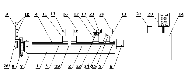
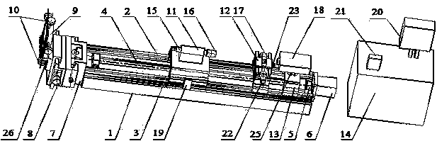
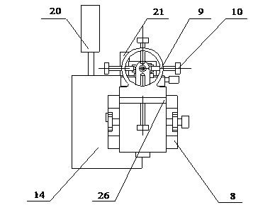
[0018] see figure 1 , image 3 and Figure 4 , the linear displacement sensor automatic calibration device of the present invention is mainly used for the automatic calibration of various types of linear displacement sensors such as rod type and rope type, and its overall structure is similar to that of a general-purpose CNC machine tool.

[0019] The linear displacement sensor automatic calibration device of the present invention includes a base (1), a double linear guide rail (2), a grating ruler (3), a ball screw (4), a shaft coupling (5), a servo motor (6), Vertical lifting device (7), horizontal adjustment device (8), universal fixture (9), lock nut (10), automation console (14), control panel (20), electronic handwheel (21), laser calibration mechanism The laser calibration mechanism includes a sliding laser mirror support frame (11), a sliding laser interference mirror support frame (12), a sliding dual-frequency laser interferometer support frame (13), a fixed pull r...

Embodiment 2

[0021] On the basis of Embodiment 1, the linear displacement sensor automatic calibration device also includes an adjusting bolt (22) and an adjusting nut (25), and the adjusting bolt (22) is fixed on the sliding interference mirror support frame ( 12) is used for the adjustment of the laser interference mirror (17). After the adjustment is completed, it is locked by the lock nut (23) fixed on the sliding interference mirror support frame (12); the adjustment nut (25) is fixed On the sliding dual-frequency laser interferometer support frame (13), the adjustment nut (25) is fixed on the sliding dual-frequency laser interferometer support frame (13) for dual-frequency laser interference The adjustment of the instrument (18) is locked by the lock nut (24) fixed on the sliding dual-frequency laser interferometer support frame (13) after the adjustment; the number of lock nuts (10) is four, The circumferential distribution is installed on the universal clamp (9). The electronic ha...


PUM


Abstract

The invention discloses an automated linear displacement sensor calibration device which mainly comprises a substrate, and dual linear guide rails, a grating ruler, a servo motor and a vertical lifting device which are fixed on the substrate; a roller screw rod is connected with the servo motor by a coupler; a horizontal regulation device, a universal clamp and a locking nut are clamped with one another and are connected with the vertical lifting device; a sliding laser reflection mirror support frame, a sliding laser interferoscope support frame and a sliding dual-frequency laser interferometer support frame are fixed on the linear guide rails; a fixed pull rod, a laser reflection mirror and a grating ruler reading sensor are fixed on the sliding reflection mirror support frame; a laser interferoscope is fixed on the sliding interferoscope support frame; a dual-frequency laser interferometer is fixed on the dual-frequency laser interferometer support frame. The calibration precision can be ensured by the arrangement of the laser calibration mechanism, manpower and time cost are greatly reduced, and the calibration work efficiency is enhanced.

Description


Claims


Application Information

Patent Timeline
Owner CHANGZHOU INST OF MEASUREMENT & TESTING TECH
Why Eureka
Try Eureka