
Anchorage clip for steel strand fatigue test

A fatigue test, steel strand technology, applied in the direction of measuring devices, instruments, scientific instruments, etc., can solve the problems of inability to correctly evaluate the fatigue performance of steel strands, uneven stress on steel strands, and broken steel strands, etc. The effect of avoiding fatigue source, firm and reliable clamping, and preventing fatigue fracture

Active Publication Date: 2014-03-12
济南东测试验机技术有限公司 +1
View PDF3 Cites 3 Cited by
  • Summary
  • Abstract
  • Description
  • Claims
  • Application Information

AI Technical Summary

Problems solved by technology

[0002] At present, most domestic steel strand fatigue performance tests use clips with ring teeth and point teeth, or directly use engineering anchor clips to clamp the steel strands. During the fatigue test, the ring teeth of the clips hold the Steel strands, but due to the uneven stress on the steel strands, indentations appear on the clamped parts and become a source of fatigue, and then the steel strands break in the chuck during the fatigue test, forming a "notch effect", and this Once this situation occurs, according to the standard of GB / T5224-2003 "Steel Strand for Prestressed Concrete", the test is invalid, so the fatigue performance of the steel strand cannot be correctly evaluated.

Method used


Image

  • Anchorage clip for steel strand fatigue test
  • Anchorage clip for steel strand fatigue test
  • Anchorage clip for steel strand fatigue test

Examples


Embodiment Construction

[0019] A further description will be given below in conjunction with the drawings.

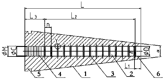
[0020] Such as figure 1 As shown, the anchor clip for the fatigue test of a steel strand of the present invention includes a plurality of clips

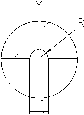
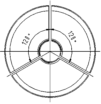
[0021] 1. It can be two or three, with a distance of 2~3mm. Now we will use three clips 1 to explain. The three clips 1 are surrounded together. The outer surface of the clip 1 is joined to form a conical surface with a narrow front and a wide rear surface, and the inner surface forms a cylindrical clamping groove 2. A ring of tightening spring fixing groove is provided at the rear of the conical surface 5. The inner surface of the clamping piece 1 at the rear of the wire clamping groove 2 is provided with annular teeth 4, and the inner surface of the clamping piece 1 in the middle and the front of the wire clamping groove 2 is provided with a plurality of side by side and spaced annular pressure relief grooves 3. The tightening spring is embedded in the...


PUM

PropertyMeasurementUnit
Cone angleaaaaaaaaaa
Spacingaaaaaaaaaa
Lengthaaaaaaaaaa

Abstract

The invention discloses an anchorage clip for a steel strand fatigue test. The anchorage clip comprises a plurality of clip bodies and clamping slots, wherein the plurality of clip bodies are enclosed together and can be extruded towards the axes; the outer surfaces of the plurality of clip bodies are spliced into a conical surface in which the front is narrow and the rear is wide, and the inner surfaces are enclosed into a cylinder; a circle of tightening spring fixing slots are arranged at the rear part of the conical surface; annular teeth are arranged at the inner surfaces of the clip bodies at the rear parts of the clamping slots; a plurality of annular pressure relief grooves which are arranged in parallel and at intervals are arranged on the inner surfaces of the clip bodies at the middle parts and the front parts of the clamping slots; a guide section is arranged at the front part of each clamping slot. The anchorage clip for the steel strand fatigue test has the beneficial effects of being firm and reliable in clamping a steel strand, and free of damage, the clamping force of the clip bodies on the steel strand is even in distribution by adopting the annular pressure relief grooves, a fatigue source is avoided, a fatigue fracture of the steel strand caused by clamping is prevented, the fatigue property of the steel strand can be correctly evaluated, meanwhile, the clip bodies are protected, and the service life is prolonged.

Description

Technical field [0001] The invention relates to an anchor clamp for steel strand fatigue test. Background technique [0002] At present, most domestic steel strand fatigue performance tests use clips with ring teeth and point teeth, or directly use engineering anchor clips to clamp the steel strand. During the fatigue test, the ring teeth of the clip clamp However, due to the uneven force of the steel strand, the clamped part appears indentation and becomes the source of fatigue. Then the steel strand breaks in the chuck during the fatigue test, forming a "notch effect", and this Once this happens, according to the standard of GB / T5224-2003 "Steel Wire for Prestressed Concrete", the test is invalid, so the fatigue performance of the steel strand cannot be correctly evaluated. Summary of the invention [0003] In order to solve the above technical shortcomings, the present invention provides an anchor clamp for fatigue test of the steel strand that can firmly and reliably clamp th...

Claims


Application Information

Patent Timeline
IPC IPC(8): G01N3/04
Inventor 陈楠王文喜毛爱菊霍原洪郑寿智王旭东王莉
Owner 济南东测试验机技术有限公司
Learn More