Machine tool and clamping jig thereof

A technology for machine tools and bed bodies, applied in the field of clamping fixtures of machine tools, can solve the problems of axial dimensional deviation of rotating shafts, low rigidity of pipe fittings, affecting machining accuracy and quality, etc., and achieves the effect of reliable clamping and accurate positioning.

Active Publication Date: 2017-06-09
KUNSHAN YUNCO PRECISION IND TECH
View PDF6 Cites 2 Cited by
  • Summary
  • Abstract
  • Description
  • Claims
  • Application Information

AI Technical Summary

Problems solved by technology

For pipe fittings with an outer diameter of less than 0.5mm, the rotating shaft of the pneumatic three-jaw chuck structure is rarely used because the contact surface of the jaws is very small when the pipe is clamped, and the repeat positioning accuracy is low; the spring chuck structure is used The rotating shaft is used to clamp and process precision thin-walled tubes with ultra-small outer diameters. In addition to clamping, auxiliary support fixtures must be used, that is, one end of the workpiece

Method used


Image

  • Machine tool and clamping jig thereof
  • Machine tool and clamping jig thereof
  • Machine tool and clamping jig thereof

Examples


Example Embodiment

[0029] The embodiments of the present invention will be described in detail below. Examples of the embodiments are shown in the accompanying drawings, wherein the same or similar reference numerals indicate the same or similar elements or elements with the same or similar functions. The embodiments described below with reference to the drawings are exemplary, and are only used to explain the present invention, but should not be understood as limiting the present invention.

[0030] In the description of the present invention, it should be understood that the terms "center", "longitudinal", "transverse", "upper", "lower", "front", "rear", "left", "right", " The orientation or positional relationship indicated by "vertical", "horizontal", "top", "bottom", "inner", "outer" etc. is based on the orientation or positional relationship shown in the drawings, and is only for the convenience of describing the present invention and The description is simplified, rather than indicating or i...


PUM


Abstract

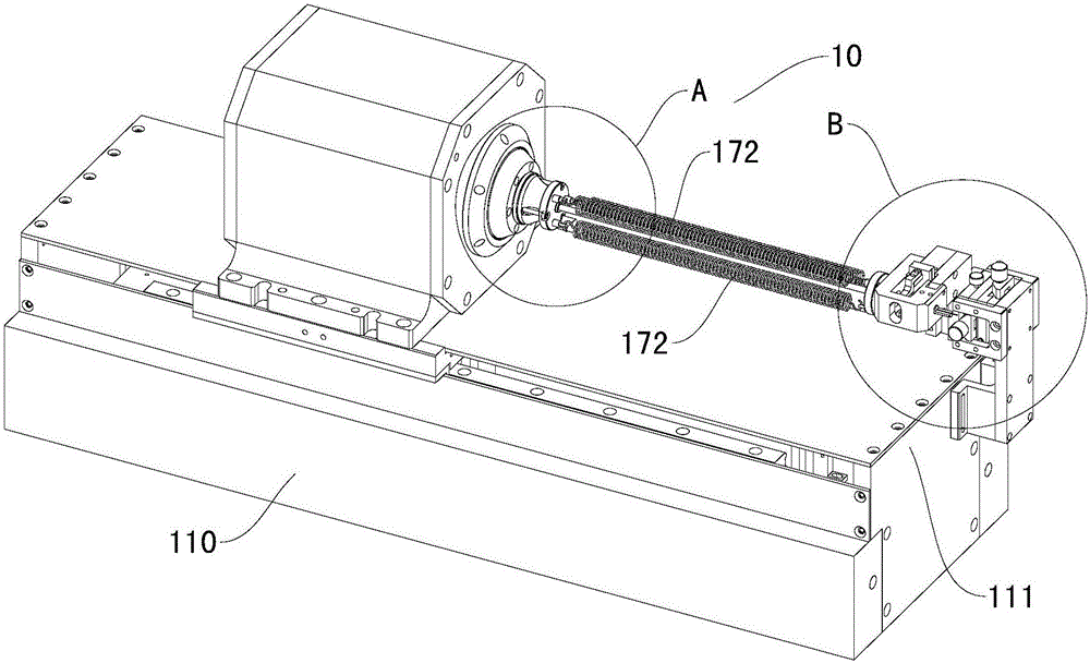
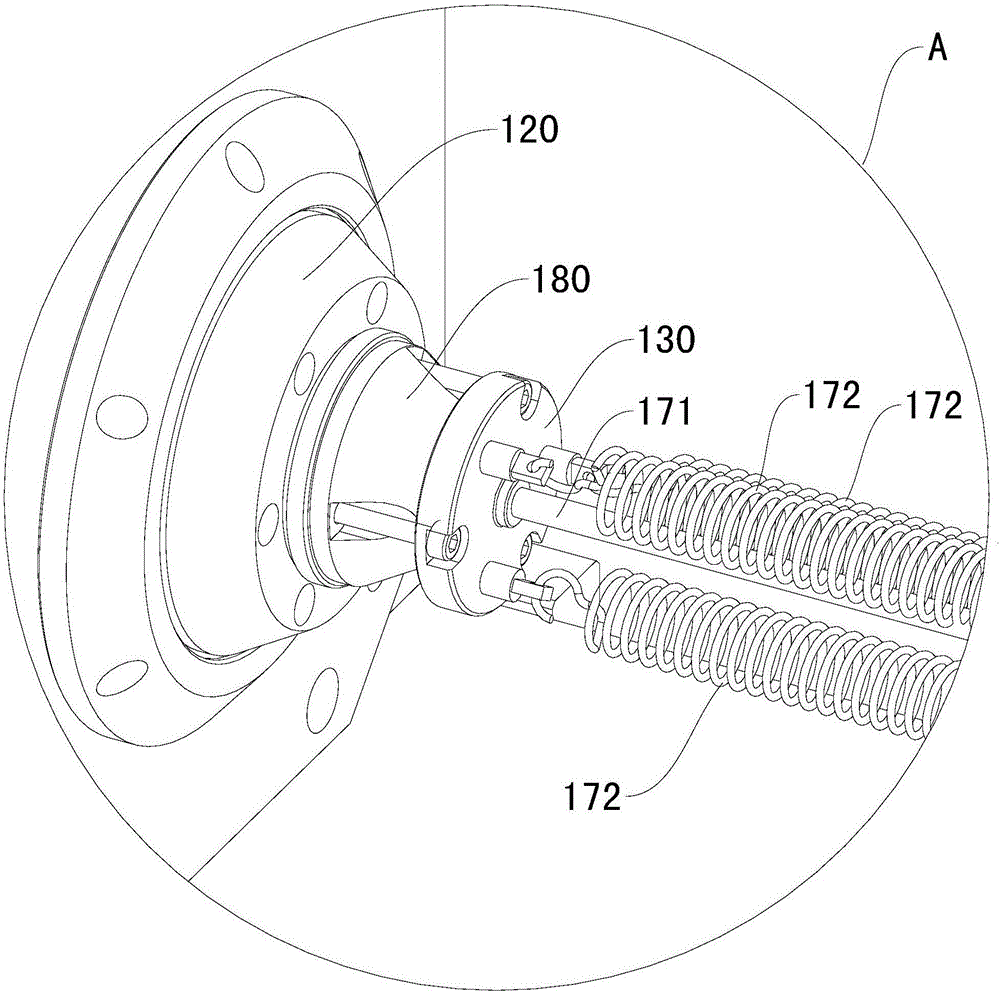
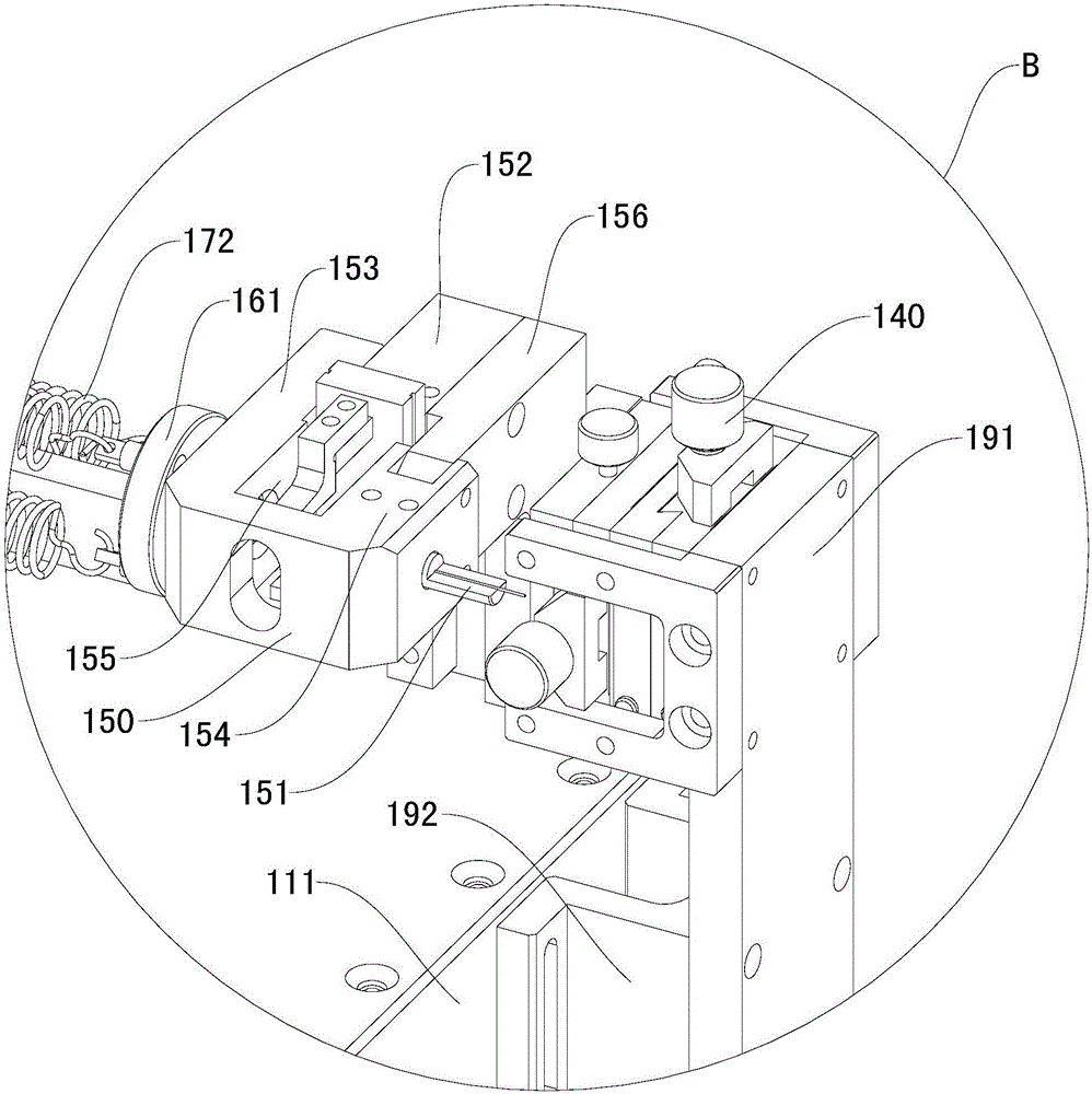
The invention discloses a machine tool and a clamping jig thereof. The machine tool comprises a lathe bed, a rotary shaft, a transition base, a two-dimensional adjusting device, a mounting seat, a rotary connecting seat, a hollow elastic pipe and a plurality of elastic parts. An X-axis motion platform is arranged on the lathe bed. The rotary shaft is arranged on the X-axis motion platform in the direction X in the manner of being capable of doing reciprocating motion. The transition base is arranged on the rotary shaft. The two-dimensional adjusting device is arranged on the X-axis motion platform. The mounting seat is arranged on the two-dimensional adjusting device. The rotary connecting seat is rotationally arranged on the mounting seat. The first end of the hollow elastic pipe is arranged on the transition base, and the second end of the hollow elastic pipe is arranged on the rotary connecting seat. The multiple elastic parts are arranged around the hollow elastic pipe, the first end of each elastic part is arranged on the transition base, and the second end of each elastic part is arranged on the rotary connecting seat. The machine tool has the beneficial effects of being firm in clamping, accurate in locating, stable, reliable and the like, and the defects that when an existing machine tool jig clamps thin and long workpieces, the middles of the workpieces are concave, and butt joint dislocation happens during continuous machining are completely avoided.

Description

technical field [0001] The invention relates to the field of machining, in particular to a machine tool for machining precision workpieces, and also to a clamping fixture for the machine tool. Background technique [0002] As a precision professional tool used by CNC machine tools to control the position and movement of the workpiece, the clamping fixture itself is designed and processed directly determines the quality of the workpiece to be processed. With the rapid development of Industry 4.0 technology, the processing capacity and production demand for precision parts, especially precision thin-walled tube parts with extremely small outer diameters, are gradually increasing. Conventional clamping methods and processing techniques can no longer meet the clamping and processing of small workpieces such as precision thin-walled tubes with an outer diameter of less than 0.5 mm. The field of ultra-micro-machining technology has increasingly become the focus and difficulty of r...

Claims


Application Information

Patent Timeline
IPC IPC(8): B23K26/38
CPCB23K26/38
Inventor 胡罡蔡猛夏发平
Owner KUNSHAN YUNCO PRECISION IND TECH
Why Eureka
Try Eureka