Control device and method for low vortex shaft ultrasonic cleaning equipment of aero-engine
What is Al technical title?
Al technical title is built by PatSnap Al team. It summarizes the technical point description of the patent document.
An aero-engine, ultrasonic cleaning technology, applied in non-electric variable control, cleaning methods and utensils, cleaning methods using liquids, etc. Such problems as cleaning requirements for similar parts and blisk parts to achieve the effect of improving service life and reliability and improving production efficiency
Inactive Publication Date: 2015-11-04
SHENYANG LIMING AERO-ENGINE GROUP CORPORATION
View PDF5 Cites 0 Cited by
Summary
Abstract
Description
Claims
Application Information
AI Technical Summary
This helps you quickly interpret patents by identifying the three key elements:
Problems solved by technology
Method used
Benefits of technology
Problems solved by technology
[0002] The control system of the low vortex ultrasonic cleaning equipment is to control the cleaning equipment to complete the cleaning of the long shaft parts and blisk parts of the aero-engine, so as to meet the surface cleanliness requirements before the parts are assembled. At present, the ultrasonic cleaning equipment in the domestic market has low power , the operating system cannot meet the cleaning requirements of aero-engine long shaft parts and blisk parts, which greatly affects the engine assembly and test run process, and there is no ultrasonic cleaning control device directly used only for aero-engine low-turbine shafts
Method used
Image
Click on the blue label to locate the original text in one second.
Reading with bidirectional positioning of images and text.
Examples
Embodiment Construction
[0029] An embodiment of the invention will be further described below in conjunction with the accompanying drawings.
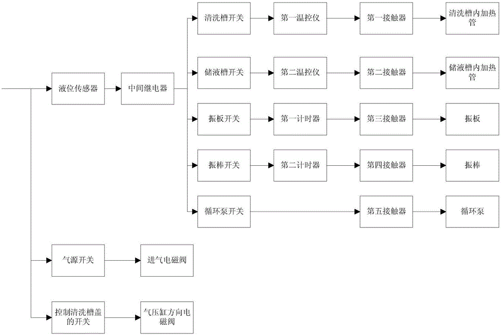
[0030] Such as figure 1 As shown, a control device for an aero-engine low vortex ultrasonic cleaning equipment includes a liquid level sensor, an intermediate relay, a first temperature controller, a second temperature controller, a first temperature sensor, a second temperature sensor, a first timer timer, second timer, first contactor, second contactor, third contactor, fourth contactor, fifth contactor, intake solenoid valve, pneumatic cylinder direction solenoid valve, cleaning tank switch, liquid storage tank Switches, vibrating plate switches, vibrating rod switches, circulating pump switches, gas source switches and switches used to control the cleaning tank cover; in the embodiment of the present invention, the liquid level sensor adopts the 0KD-1075S model; the intermediate relay adopts the RY4S-U model; The cleaning tank switch, liquid storage tank ...
PUM
Abstract
The invention belongs to a control device and method for ultrasonic cleaning equipment of a low turboshaft of an aviation motor and belongs to the technical field of aviation motors. The device comprises a liquid level sensor, a medium relay, a first temperature control instrument, a second temperature control instrument, a first temperature sensor, a second temperature sensor, a first timer, a second timer, a first contactor, a second contactor, a third contactor, a fourth contactor, a fifth contactor, an air inlet solenoid valve, an air pressure cylinder direction solenoid valve, a cleaning slot switch, a liquid storing slot switch, a vibration plate switch, a vibration bar switch, a circulation pump switch, an air source switch and a switch for controlling the cover of a cleaning slot. The control device and method for the ultrasonic cleaning equipment of the low turboshaft of the aviation motor have the functions of automatic temperature controlling on cleaning liquid, liquid level alarming and protecting, ultrasonic work timing and electric leakage protecting, and ensures the smooth assembly of the motor; the production efficiency of parts of the motor is improved after the parts are cleaned, the service life and the reliability are improved, and the development demands of the national aviation industry are met.
Description
technical field [0001] The invention belongs to the technical field of aero-engines, and in particular relates to a control device and method for an aero-engine low-turbine ultrasonic cleaning device. Background technique [0002] The control system of the low vortex ultrasonic cleaning equipment is to control the cleaning equipment to complete the cleaning of the long shaft parts and blisk parts of the aero-engine, so as to meet the surface cleanliness requirements before the parts are assembled. At present, the ultrasonic cleaning equipment in the domestic market has low power , the operating system cannot meet the cleaning requirements of aero-engine long shaft parts and blisk parts, which greatly affects the engine assembly and test run process, and there is no ultrasonic cleaning control device directly used only for aero-engine low-turbine shafts. Contents of the invention [0003] Aiming at the deficiencies in the prior art, the present invention provides a control ...
Claims
Application Information
Patent Timeline
Application Date:The date an application was filed.
Publication Date:The date a patent or application was officially published.
First Publication Date:The earliest publication date of a patent with the same application number.
Issue Date:Publication date of the patent grant document.
PCT Entry Date:The Entry date of PCT National Phase.
Estimated Expiry Date:The statutory expiry date of a patent right according to the Patent Law, and it is the longest term of protection that the patent right can achieve without the termination of the patent right due to other reasons(Term extension factor has been taken into account ).
Invalid Date:Actual expiry date is based on effective date or publication date of legal transaction data of invalid patent.
Patent Type & Authority Patents(China)
IPC IPC(8): G05D27/02G05B19/04B08B3/12
Inventor 秦洪运郭旭宋伟崔艳敏王毓
Owner SHENYANG LIMING AERO-ENGINE GROUP CORPORATION