High-efficiency, high-gain, and low-voltage and current-stress dc-dc converters
What is AI technical title?
AI technical title is built by PatSnap AI team. It summarizes the technical point description of the patent document.
A DC-DC, current stress technology, applied in the direction of conversion equipment without intermediate conversion to AC, can solve the problems of difficult to achieve soft switching, high voltage stress of the switch tube, and reduce the efficiency of the converter, so as to solve the problem of reverse recovery , low voltage stress, and improved efficiency
Active Publication Date: 2016-04-13
SOUTH CHINA UNIV OF TECH
View PDF7 Cites 0 Cited by
Summary
Abstract
Description
Claims
Application Information
AI Technical Summary
This helps you quickly interpret patents by identifying the three key elements:
Problems solved by technology
Method used
Benefits of technology
Problems solved by technology
At present, high-gain non-isolated DC-DC converters mainly include switched capacitor type and switched inductor type. The voltage can be increased by adding switched capacitors or inductors, but it is difficult to achieve soft switching, which reduces the efficiency of the converter.
The secondary boost converter can achieve high gain and is also very popular, but the voltage stress of the switch tube is very large, which limits the further increase of the voltage
In addition, high gain can also be achieved through coupled inductors, but the leakage inductance of coupled inductors is difficult to control, which will increase the voltage stress and energy loss of the switch tube
Method used
Image
Click on the blue label to locate the original text in one second.
Reading with bidirectional positioning of images and text.
Examples
Embodiment Construction
[0013] In order to further illustrate the content and features of the present invention, the specific embodiments of the present invention will be described in detail below in conjunction with the accompanying drawings. But the implementation of the present invention is not limited thereto.
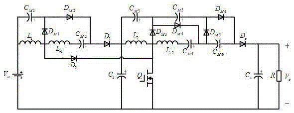
[0014] refer to figure 1 , the DC-DC converter with high efficiency, high gain and low voltage current stress of the present invention, with DC power supply V in , switch tube Q, first diode D 1 , the second diode D 2 , the fourth diode D M1 , the fifth diode D M2 , the first inductance L 1 , the third inductance L r1 , the first capacitance C 1 , the third capacitor C M1 and the fourth capacitor C M2 The input stage Boost converter constituted; with the first capacitor C 1 , switch tube Q, third diode D o , the sixth diode D M3 , the seventh diode D M4 , the eighth diode D M5 , the ninth diode D M6 , the second inductance L 2 , the fourth inductance L r2 , the fifth capa...
PUM
Abstract
The invention provides a DC-DC (Direct Current to Direct Current) converter with high efficiency, high gain and low voltage and current stresses. In the DC-DC converter, a direct-current power supply, a switch tube, a first diode, a second diode, a fourth diode, a fifth diode, a first inductor, a third inductor, a first capacitor, a third capacitor and a fourth capacitor construct an input-grade Boost converter; the first capacitor, the switch tube, a third diode, a sixth diode, a seven diode, an eighth diode, a ninth diode, a second inductor, a fourth inductor, a fifth capacitor, a sixth capacitor, a seventh capacitor, an eighth capacitor, a second capacitor and a load construct an output grade Boost converter. The input Boost converter and the output Boost converter are connected to the second inductor and the fourth inductor to serve as resonant inductors, so that the zero current turning-on of the switch tube is realized; meanwhile, the zero current turning-off of each diode is realized. The gain of the converter is 6 / (1-D)2, and the voltage stress of the switch tube is one third that of the output voltage.
Description
technical field [0001] The invention relates to the field of high-gain non-isolated DC-DC converters, in particular to a DC-DC converter with high efficiency, high gain and low voltage and current stress. Background technique [0002] In recent years, high-gain non-isolated DC-DC converters are widely used in UPS, distributed photovoltaic power generation and battery energy storage systems. At present, high-gain non-isolated DC-DC converters mainly include switched capacitor type and switched inductor type. The voltage increase is achieved by adding switched capacitors or inductors, but it is difficult to achieve soft switching, which reduces the efficiency of the converter. The secondary boost converter can achieve high gain and is also very popular, but the voltage stress of the switch tube is very large, which limits the further increase of the voltage. In addition, a high gain can also be achieved through a coupled inductor, but the leakage inductance of the coupled ind...
Claims
Application Information
Patent Timeline
Application Date:The date an application was filed.
Publication Date:The date a patent or application was officially published.
First Publication Date:The earliest publication date of a patent with the same application number.
Issue Date:Publication date of the patent grant document.
PCT Entry Date:The Entry date of PCT National Phase.
Estimated Expiry Date:The statutory expiry date of a patent right according to the Patent Law, and it is the longest term of protection that the patent right can achieve without the termination of the patent right due to other reasons(Term extension factor has been taken into account ).
Invalid Date:Actual expiry date is based on effective date or publication date of legal transaction data of invalid patent.

