Multimode wireless terminal and its method for initiating circuit domain voice service

A technology for wireless terminals and voice services, applied in wireless communications, electrical components, access restrictions, etc., can solve the problems of increased call connection delay, increased call setup time, and impact on user experience, etc. The effect of reducing signal loss

Active Publication Date: 2016-08-24
SPREADTRUM COMM (SHANGHAI) CO LTD
View PDF4 Cites 0 Cited by
  • Summary
  • Abstract
  • Description
  • Claims
  • Application Information

AI Technical Summary

Problems solved by technology

Compared with the traditional 2G / 3G voice call, when the terminal falls back from LTE to the 2G / 3G network in the CSFB scheme, there are additional processes such as measurement, synchronization and system message reading of the 2G / 3G target cell, even including location area update ( LU) process, resulting in an increase of call connection delay of 1 to 4 seconds, resulting in a long call connection time or even more than 10 seconds, and poor user experience
In addition, the call setup time increases, and there is a risk of a reduced call setup success rate;
[0007] (2) It takes a long time to return to LTE after the call ends
After the voice service ends on the 2G / 3G network, it returns to the LTE network through reselection. There is a second-level unreachable time, and the terminal cannot perform communication services, which affects user experience;
[0008] (3) If GSM (Global System of Mobile Communication, Global System for Mobile Communication) is dropped, voice and data services cannot be concurrent
[0009] (3) If GSM is dropped back, since the voice and data services cannot be concurrent, the calling and called services of the PS cannot be carried out

Method used


Image

  • Multimode wireless terminal and its method for initiating circuit domain voice service
  • Multimode wireless terminal and its method for initiating circuit domain voice service
  • Multimode wireless terminal and its method for initiating circuit domain voice service

Examples


Embodiment Construction

[0049] In the following description, many technical details are proposed in order to enable readers to better understand the application. However, those skilled in the art can understand that without these technical details and various changes and modifications based on the following implementation modes, the technical solution claimed in each claim of the present application can be realized.

[0050] In order to make the purpose, technical solution and advantages of the present invention clearer, the following will further describe the implementation of the present invention in detail in conjunction with the accompanying drawings.

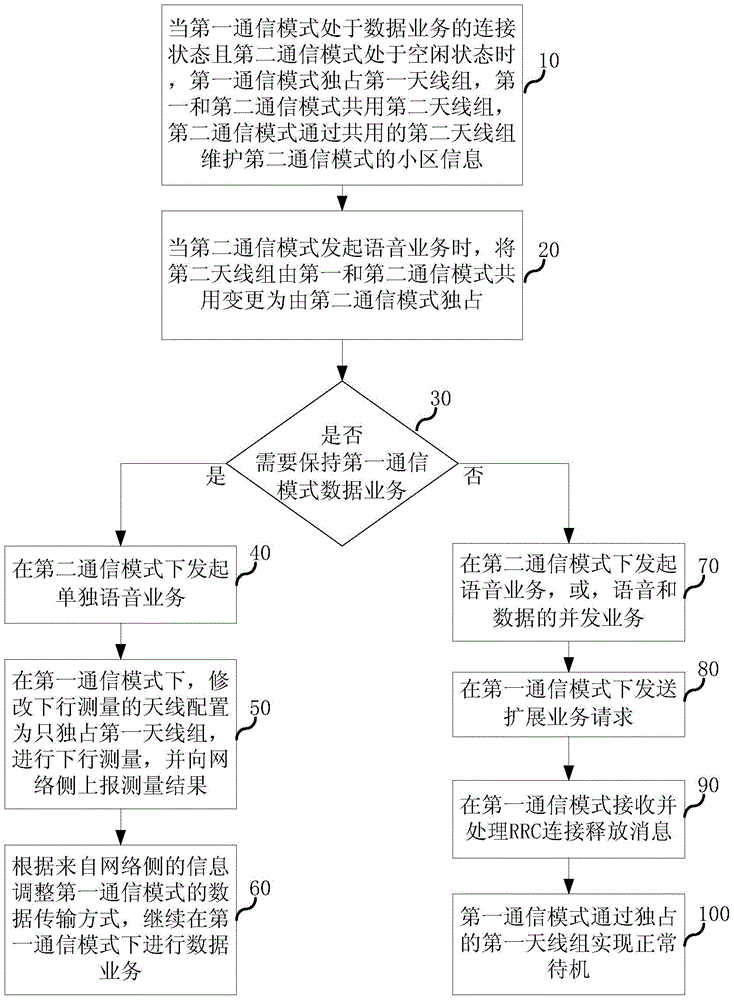
[0051] figure 1 It is a schematic flowchart of a method for a multi-mode wireless terminal to initiate a CS domain voice service through CS domain fallback in the present invention. The wireless terminal in this method supports at least the first communication mode and the second communication mode, the second communication mode supports circuit ...


PUM


Abstract

The invention relates to the field of wireless communication, and discloses a multi-mode wireless terminal and a method for initiating circuit domain voice services. In the present invention, the method includes the following steps: when the first communication mode is in the connected state of the data service and the second communication mode is in the idle state, the first communication mode exclusively occupies the first antenna group, and the first and second communication modes share the first antenna group. Two antenna groups, the second communication mode maintains its cell information through the second antenna group; when the second communication mode initiates a voice service, the second antenna group is changed from being shared by the first and second communication modes to being exclusively used by the second communication mode ; Maintain the data service of the first communication mode. The invention shortens the time delay of voice service call establishment of the wireless terminal when the circuit domain falls back, can quickly return to the first communication mode after the voice service ends, and can still support concurrent voice and data services after falling back to the second communication mode.

Description

technical field [0001] The invention relates to the field of wireless communication, in particular to a multi-mode wireless terminal. Background technique [0002] With the vigorous development of various Internet applications, the existing third-generation (3G, 3Generation) communication network can no longer meet the growing needs of people. Wireless communication systems are increasingly showing the development trend of mobility, broadband and Internet. Under this situation, as the fourth generation (4G, 4Generation) communication technology, LTE (Long Term Evolution, 3GPP (Third Generation Partnership Project) ) long-term evolution project) will become the direction of network evolution in the future. [0003] The LTE network is based on the Internet Protocol (IP, Internet Protocol) architecture, and can only provide voice over IP (VoIP, Voice over IP) services based on the packet domain (PS, Packet Switched). and service control capability, therefore, the IP Multimedi...

Claims


Application Information

Patent Timeline
Patent Type & Authority Patents(China)
IPC IPC(8): H04W24/02H04W48/18
Inventor 李力游康一董霄剑许佰魁
Owner SPREADTRUM COMM (SHANGHAI) CO LTD
Why Eureka
Try Eureka