Coupling method for vibrating table and shielding box body

A vibrating table and box technology, applied in the direction of magnetic/electric field shielding, electrical components, etc., can solve the problems of unsuitable finger reeds and conductive rubber pads, wear of conductive rubber pads, and reduced shielding performance

Active Publication Date: 2014-03-12
CHINA ELECTRONIS TECH INSTR CO LTD
View PDF4 Cites 3 Cited by
  • Summary
  • Abstract
  • Description
  • Claims
  • Application Information

AI Technical Summary

Problems solved by technology

[0005] 1. While the vibrating table is vibrating in the axial direction, there is also a large shaking in the radial direction, and the finger reeds and conductive rubber gaskets are not applicable in this case
[0006] 2. Finger reeds and conductive rubber pads will wear out quickly when the vibration table is performing high-frequency vibration tests
[0007] 3. The use of these two shielding methods will make the vibrating table and the shielding box form an electrical contact, destroying the screen
[0010] 1. At present, the shielding of holes and seams generally does not consider the existence of relative motion. While the moving coil of the vibrating table vibrates in the axial direction, there is also a large sway in its radial direction. At present, there is no solution for this new demand. mature technology
[0011] 2. Although the beryllium bronze finger reed and the conductive rubber gasket allow relative movement at the shielded hole, the shielding performance is greatly reduced when there is both vibration and shaking in the connection between the vibrating table and the shielding box.
[0013] 4. The use of these two shielding methods will make the vibration table and the shielding box form electrical contact, destroying the original grounding method of the shielding box

Method used


Image

  • Coupling method for vibrating table and shielding box body
  • Coupling method for vibrating table and shielding box body
  • Coupling method for vibrating table and shielding box body

Examples


Embodiment 1

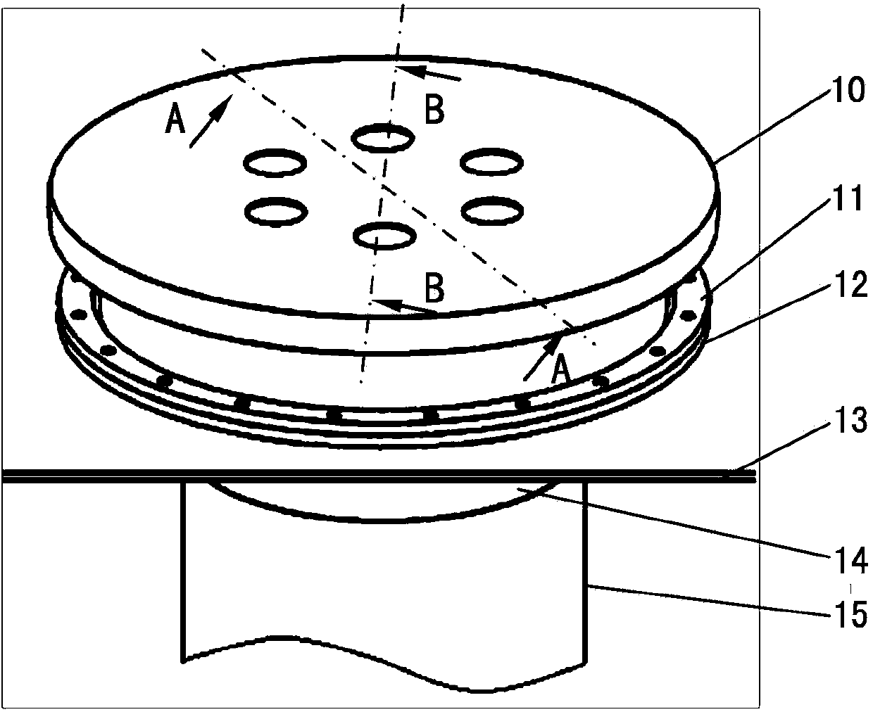
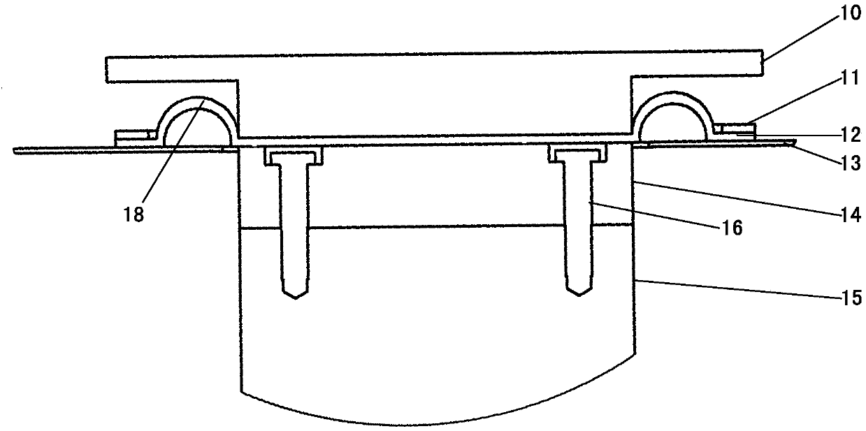
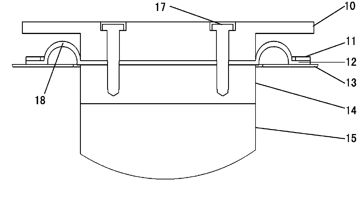
[0035] Such as Figure 1-Figure 3 As shown, holes are opened at the connection between the shielding box 13 and the vibrating table according to the size of the vibrating table moving coil 15, and enough allowance is left to meet the shaking of the vibrating table moving coil 15 in the radial direction; The tooling made of dielectric materials with good mechanical properties is divided into upper and lower parts. The upper part 10 is located inside the shielding box 13 and is used to fix the test piece. The lower half 14 is located outside the shielding box 13 and fixed with bolts 16. On the moving coil 15 of the vibrating table, the upper and lower parts of the frock are connected by bolts 17, and the conductive rubber film 12 is sandwiched between the upper and lower parts of the frock to play a shielding role.

[0036] The conductive rubber film has both sealing and shielding properties, and is an excellent shielding material. However, the elasticity of the conductive rubbe...

Embodiment 2

[0038] On the basis of the above embodiments, further, a method for connecting a vibrating table and a shielding box is provided, including the following steps:

[0039] Step 1: set a hole at the connection between the shielding box 13 and the vibrating table according to the size of the vibrating table moving coil 15, and the opening is also provided with a predetermined margin that can satisfy the shaking of the vibrating table moving coil 15 in the radial direction;

[0040] Step 2: add tooling on the moving coil 15 of the vibrating table, and divide the tooling into an upper part 10 and a lower part 14, the upper part 10 is arranged inside the shielding box 13 for fixing Test piece; the lower half 14 is set and fixed on the vibrating table moving coil 15, and is set outside the shielding box 13;

[0041] Step 3: Arranging a conductive rubber film between the upper half 10 and the lower half 14 for shielding.

[0042] Further, the predetermined margin is 5mm-50mm, preferab...


PUM


Abstract

The invention provides a coupling method for a vibrating table and a shielding box body. The coupling method comprises the following steps: 1) forming a hole in the connection part of the shielding box body and the vibrating table according to the size of a moving coil of the vibrating table, and setting a predetermined allowance at the hole for allowing the moving coil of the vibrating table to shake in the radial direction; 2) adding a tool on the moving coil of the vibrating table, dividing the tool into an upper half part and a lower half part, arranging the upper half part in the shielding box body for fixing a test article, and fixing the lower half part on the moving coil of the vibrating table and out of the shielding box body; 3) arranging a conductive rubber film between the upper half part and the lower half part to play a shielding role, and connecting the upper half part with the lower half part by virtue of bolts. By adopting the scheme, the requirement that the moving coil of the vibrating table vibrates and shakes in the axial direction can be met while the shielding performance of the shielding box body is ensured, and the experiment and test of product performance under the coupling effect of an electric magnetic field and vibratory stress can be possible.

Description

technical field [0001] The invention belongs to the technical field of electromagnetic shielding, and in particular relates to a method for connecting a vibrating table and a shielding box. Background technique [0002] The combination of the vibrating table and the shielding box is a new situation, which brings about the problem that the moving coil of the vibrating table must vibrate in the axial direction while ensuring the shielding effectiveness. At present, there is no mature solution for this situation. [0003] Electromagnetic shielding includes magnetic field shielding, electric field shielding, and electromagnetic field shielding. Under the premise of certain shielding box materials and shapes, measures such as appropriate grounding methods, improvement of hole leakage, and proper handling of cables passing through the shielding body are generally used to improve shielding. The shielding effectiveness of the box, here, no cable passes through the shielding box, mai...

Claims


Application Information

Patent Timeline
Patent Type & Authority Applications(China)
IPC IPC(8): H05K9/00
Inventor 李中群郭荣斌贺温安乔宏志秦赞
Owner CHINA ELECTRONIS TECH INSTR CO LTD
Why Eureka
Try Eureka