
Vehicle functional component

A technology for automobiles and components, applied in the field of functional components for automobiles, can solve problems such as damage to the designability, excellent aesthetics or style, and complex structure of functional components for automobiles

Active Publication Date: 2014-03-12
FU SE VACUUM FORMING +1
View PDF11 Cites 16 Cited by
  • Summary
  • Abstract
  • Description
  • Claims
  • Application Information

AI Technical Summary

Problems solved by technology

For such parts, in order to integrate the light-emitting function, it is necessary to ensure the accommodation space of the light-emitting block, which requires a relatively complicated structure, and because it is a separate component material, the design of the functional parts for automobiles itself is damaged, and it cannot be said that Is a part of superior aesthetics or style

Method used


Image

  • Vehicle functional component
  • Vehicle functional component
  • Vehicle functional component

Examples


Embodiment 1

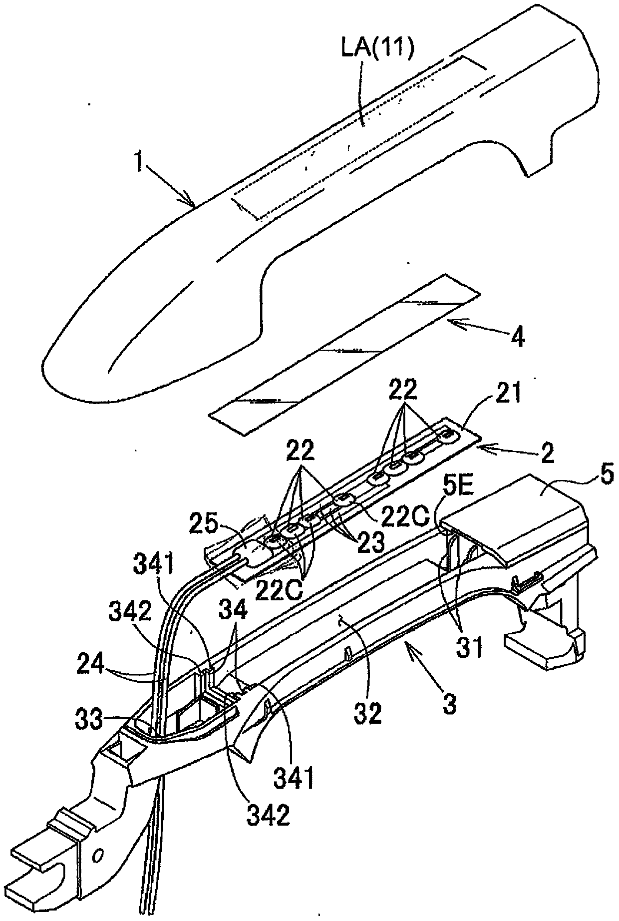
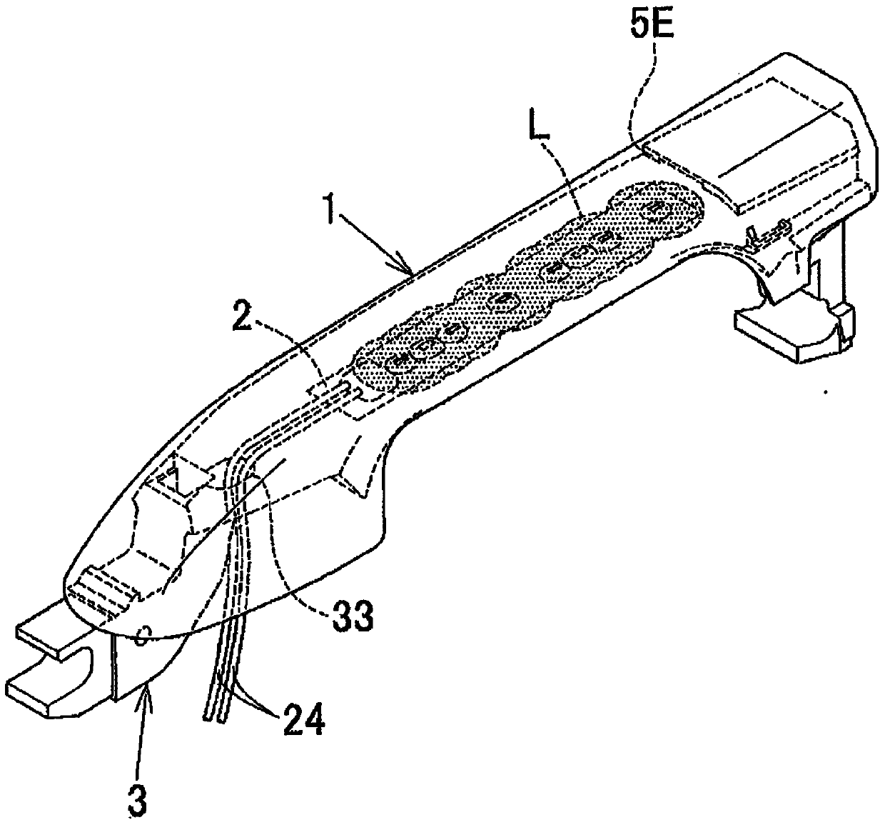
[0059] figure 1 and even Figure 4 The automotive functional part of the first embodiment shown is formed by covering the supporting frame 3 with the molded cover 1 to form the automotive door handle. The door handle is, for example, structured as follows. An electric key K (not shown) for opening and closing is built in the internal storage space 32, and a surface light source 22 composed of LED elements is arranged on the upper surface side of the electric key K. A row of elongated sheet-shaped surface light-emitting elements 2 is provided, and, along the light distribution surface as its upper surface, for example, Figure 4 The light-transmitting film 4 is processed by roughening the surface in a predetermined pattern as shown. The surface light-emitting element 2 and the light-transmitting film 4 have substantially the same shape, and are molded into an elongated rectangle along the doorknob-shaped extended upper surface of the molding cover 1 .

[0060] Here, the surf...

Embodiment 2

[0067] exist Figure 5 In the automotive functional part of the shown embodiment 2, the supporting frame 3 constitutes the automotive reflector in the state covered with the molded cover 1, and the detection part accommodated in the storage space together with the surface light-emitting element 2 detects the user's The opening and closing operation signal of the car door, or the direction indicator light operation signal. Other configurations, usage methods, and usage states not specifically described are the same as those in Embodiment 1.

Embodiment 3

[0069] exist Figure 6 In the automotive functional part of the shown embodiment 3, the support frame 3 constitutes the respective automotive door handles of the rear door or the front door in a state covered with the molded cover 1, and is accommodated together with the surface light-emitting element 2 in the storage space. The detection means detects an opening and closing operation signal of a user's automobile door or a blinker operation signal. exist Figure 6 In the figure, the rear door and the front door each project a horizontally elongated rectangular rod-shaped transmissive light-emitting part L at the same height. Other configurations, usage methods, and usage states not specifically described are the same as those in Embodiment 1.


PUM


Abstract

The invention aims to obtain a light-emitting function of a vehicle functional component with a relatively simple structure and in a relatively compact form. In addition, provided is a vehicle functional component excellent in sense of beauty and appearance without impairing the designability of the vehicle functional component itself. The vehicle component is characterized by comprising: a molded cover (1) molded into a surface shape of a component to be attached to a vehicle; and a surface light-emitting element (2) fixed by being bonded or fitted into along the back surface of the molded cover (1). In the vehicle component, the molded cover (1) is formed by decorating and molding a translucent resin mold material with a translucent film, and light from the surface light-emitting element (2) transmits the molded cover (1) and emerges in a predetermined light-emitting region which is a part of the surface of the vehicle component.

Description

technical field [0001] The invention relates to automobile reflectors, rearview mirror covers, rearview mirrors for motorcycles, automobile door handles, mounting frames for door handles, fuel filler caps, exposed fuel filler caps, water tank guards, side pillars (A pillars, B pillars) pillars, C-pillars), side moldings, rear trims, emblems, panel frames, antennas, fenders, display lamp covers, various instruments, various operating levers, etc. Its own function, or the functional parts for automobiles that constitute the exterior parts of automobiles and motorcycles, especially the parts that have a light-emitting function inside. Background technique [0002] Conventionally, an auxiliary direction indicator and side illuminating device for automobiles has been disclosed as a functional part for automobiles (see Patent Document 1), which has an auxiliary direction indicator connected to a direction indicator switch to flash on the lower part of the mounting base of the refl...

Claims


Application Information

Patent Timeline
IPC IPC(8): B60Q1/32B60R13/00E05B1/00B60Q1/34B60J5/04B60Q1/00
CPCF21S48/2243B60Q1/46B60Q1/2661E05B17/10B60Q1/50B60Q1/2669B60Q1/2665F21S48/215E05B85/16B60R13/04B60Q1/34F21S48/2268F21S43/14F21S43/239F21S43/245B60Q1/543B60Q1/32B60J5/04B60R13/00E05B1/00
Inventor 三浦高行上池义广大贺祐一
Owner FU SE VACUUM FORMING
Learn More