Crowd control barrier

A crowd, barrier technology, applied in the field of said belt-to-spool connection, able to solve problems such as spring damage, disassembly and reassembly

Active Publication Date: 2014-03-12
劳伦斯·P·韦特恩
View PDF6 Cites 7 Cited by
  • Summary
  • Abstract
  • Description
  • Claims
  • Application Information

AI Technical Summary

Problems solved by technology

But in this design, this is difficult to achieve and requires disassembly and reassembly of the entire mechanism
[0004] Another known problem with barriers of the above type is that the webbing should be fully retracted (except for one end piece) when the barrier is not in use
A particular dis...

Method used


Image

  • Crowd control barrier
  • Crowd control barrier
  • Crowd control barrier

Examples


Embodiment Construction

[0033] best practice

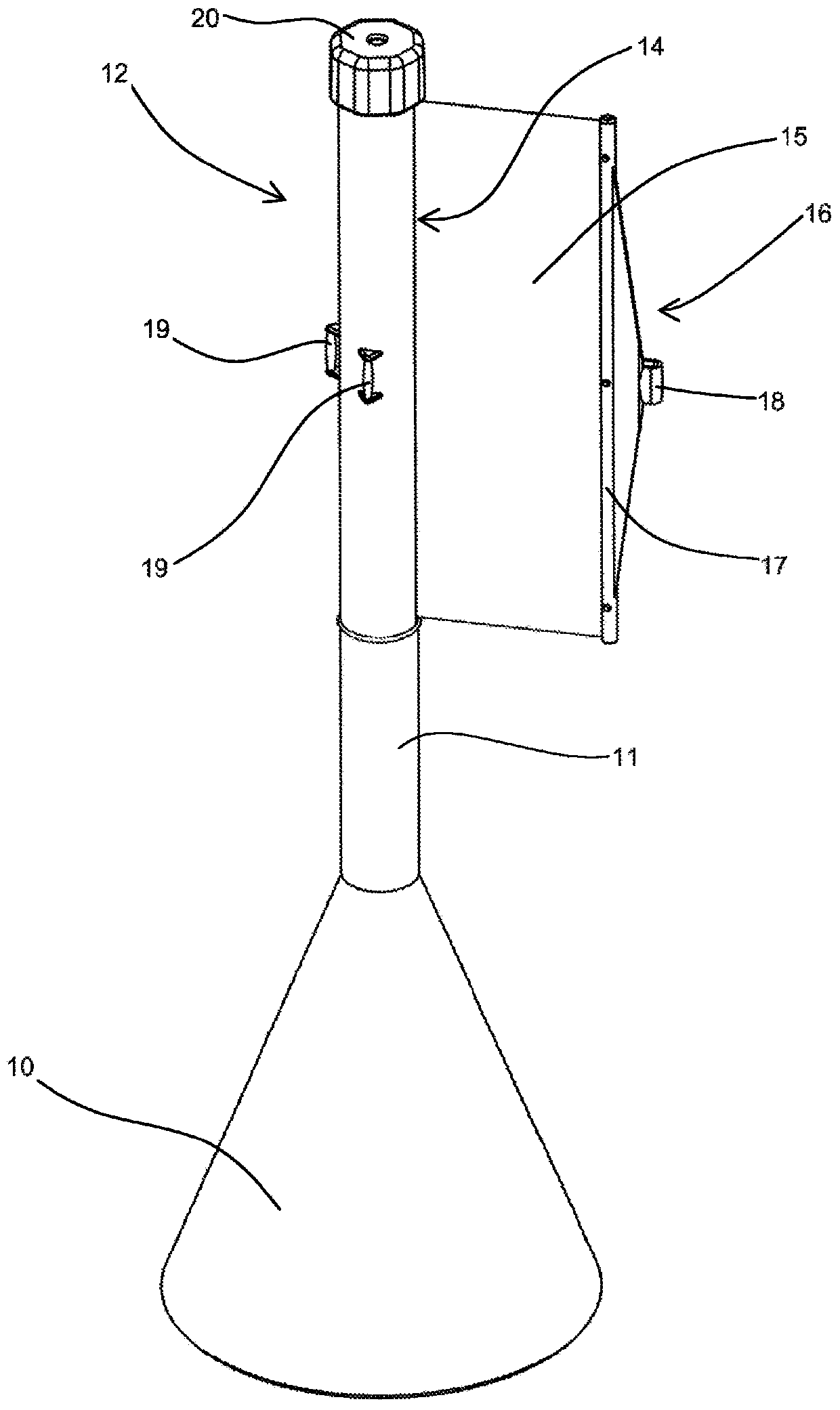
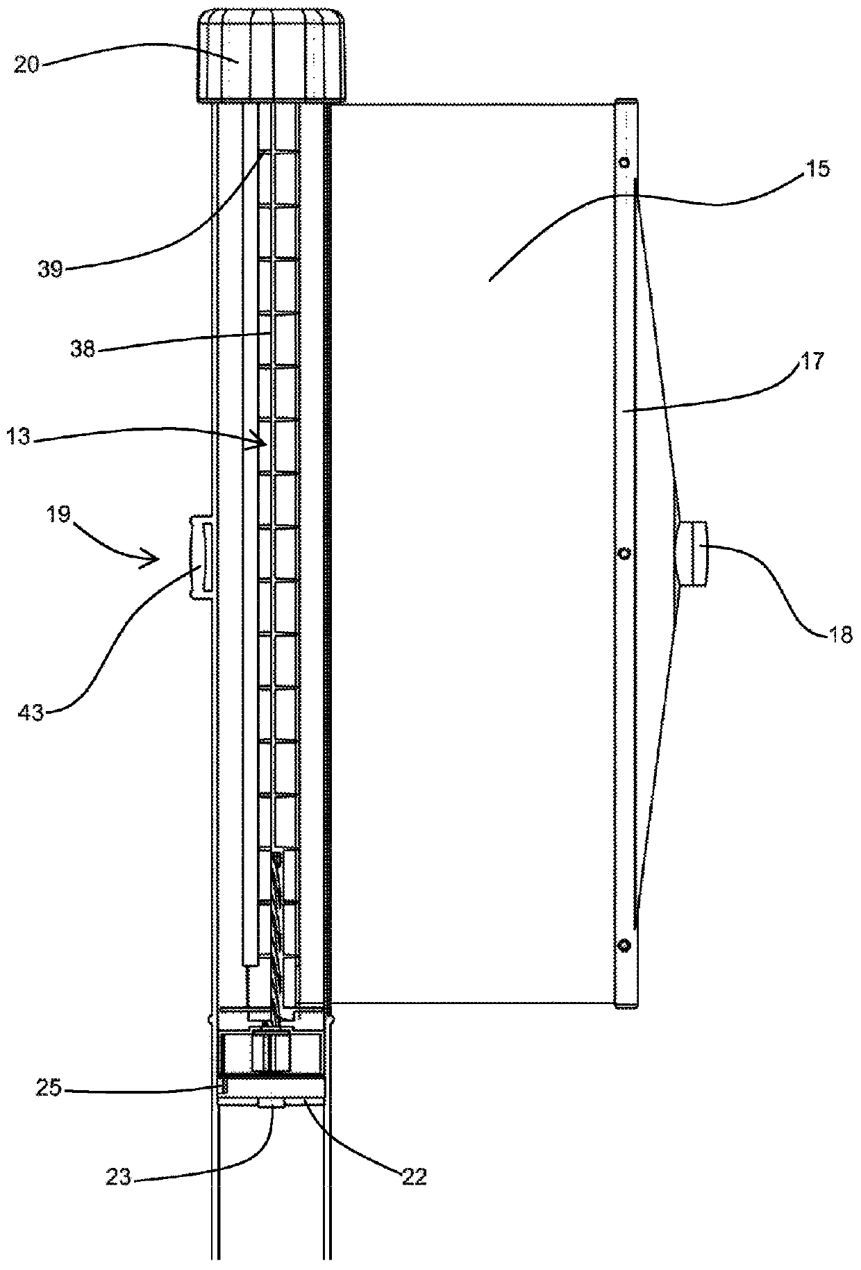
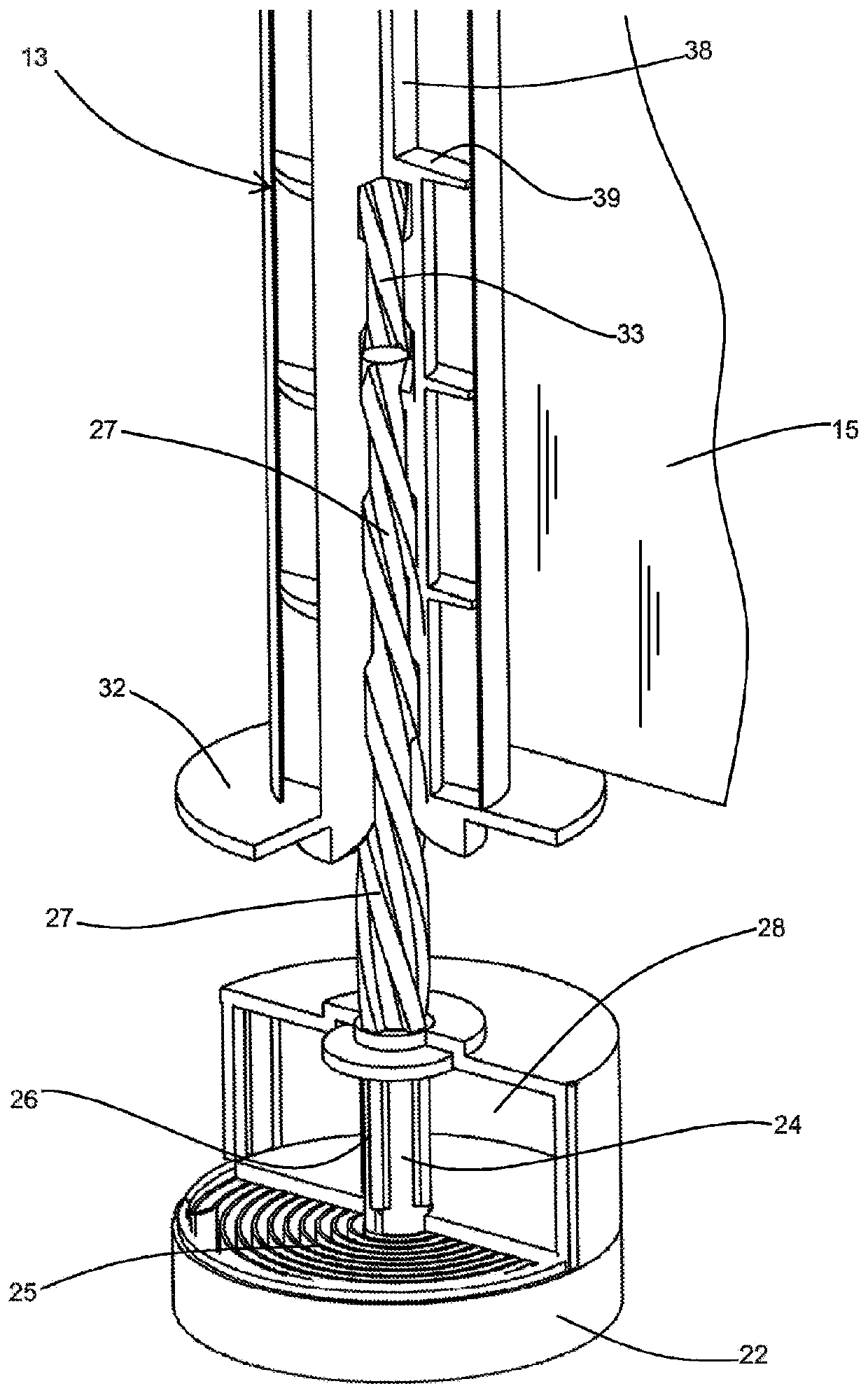
[0034] figure 1 is a general view of an embodiment of a barrier post incorporating aspects of the invention. The column comprises a generally conical base 10 from the top of which a tube 11 protrudes upwards. The upper region 12 of the tube 11 is structured as follows: The holder assembly for the spool 13 ( figure 2 ), an axial slot 14 is formed through the wall of the upper region of the tube, and a tape or film 15 wound on a bobbin 13 may extend through the slot. The free end 16 of the strap 15 is secured to a rod 17, including a clip 18 to allow said rod to be connected to some other support, such as another similar post. For this purpose, three retaining lugs 19 are provided at intervals around the upper region 12 of the tube, to which clips 18 of a strap of another barrier column can be fastened. The open upper end of the upper region 12 of the tube 11 is closed with a cap 20 between which there is a bayonet connection allowing the cap to be de...


PUM


Abstract

A holder assembly for a crowd control barrier has a bobbin (13) rotatably mounted within a container (12) and configured to have a flexible band (15) wound therearound with the free end (16) of the band emerging from the container whereby the band may be extended so that the free end can be connected to a remote support. When assembled, a spring (25) acts on the bobbin (13) such that tension in the spring is increased as the band (15) is extended whereby the spring may re-wind the band on to the bobbin. The bobbin (13) is axially insertable into and removable from the container (12) to allow the band to be changed. The spring (25) is associated with a carrier (24) and there is a screw-threaded mechanism (27) arranged to rotate the carrier (24) to pre-load the spring (25), as the bobbin (13) is inserted into the container (12).

Description

technical field [0001] The present invention relates to various aspects of crowd control barriers. In particular, the present invention relates to a retainer assembly for a crowd control barrier in the form of a strap extending from a spool located within the assembly, and also to the connection of said strap to the spool. Background technique [0002] Crowd control barriers are known to have webbing or straps closed on top of vertically extending columns, said webbing being wound on spools rotatably mounted within said columns. From seat belt technology barriers have been developed in which a spring is arranged to provide a rotational moment to the spool to wind the webbing back onto the spool. The free end of the webbing is fitted with a clip enabling the webbing to be pulled out against spring pressure and then attached to a suitable fitting provided on a similar post or some other support. [0003] According to the known barriers mentioned above, the webbing is usually...

Claims


Application Information

Patent Timeline
IPC IPC(8): E01F13/02
CPCE01F13/022E01F13/028
Inventor 劳伦斯·P·韦特恩
Owner 劳伦斯·P·韦特恩
Why Eureka
Try Eureka