Disk cover positioning cervical traction frame

A cervical vertebra traction and positioning technology, applied in the field of medical devices, can solve the problems of deviation, difficulty and inconvenient operation of the occipital-mandibular belt, and achieve the effects of preventing deviation, improving stability and easy operation.

Inactive Publication Date: 2015-09-23
梁兴斌
View PDF4 Cites 0 Cited by
  • Summary
  • Abstract
  • Description
  • Claims
  • Application Information

AI Technical Summary

Problems solved by technology

[0003] 1. Unable to achieve precise positioning
There must be a large interval between the grooves of the crossbar, so that the partition between adjacent grooves has a certain strength to withstand the lateral pressure generated by the hanging ring, and this interval makes the hanging ring in the horizontal direction. The length of the horizontal displacement on the bar must be an integral multiple of the interval, which makes the horizontal position of the occiput-maxillary belt impossible to accurately locate
[0004] 2. It is impossible to adjust the horizontal position of the occiput and jaw strap conveniently
This is very inconvenient when the patient's head is already in the occipital-maxillary strap, and it is even more difficult if the patient is asked to adjust to their own comfort because it requires the patient to reach over the top of the head to see the eyes. Operate from an invisible location
[0005] 3. Poor stability of the occipital and maxillary belt after positioning
Since the occiput-chin strap is positioned by the hanging ring on its top, and the hanging ring is in the groove of the cross bar, although the upper beam of the hanging ring cannot move along the longitudinal direction of the cross bar, it can move along the transverse direction of the cross bar. The lateral movement of the hanging ring will cause the deviation of the occipital and maxillary belt, which will cause discomfort to the patient and affect the effect of the treatment

Method used


Image

  • Disk cover positioning cervical traction frame

Examples


Embodiment Construction

[0028] The present invention will be further described below in conjunction with the accompanying drawings and embodiments.

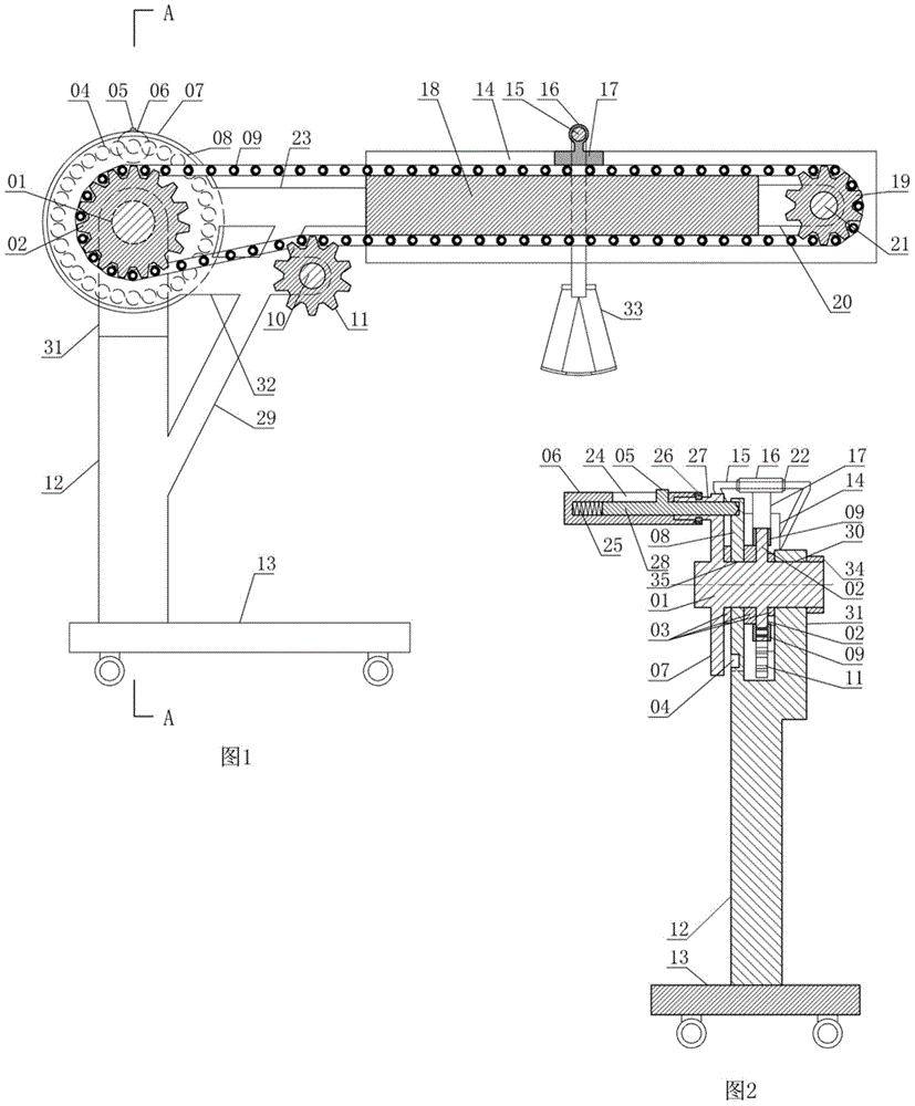
[0029] The disk cover positioning type cervical traction frame consists of main shaft 01, main gear 02, washer 03, positioning hole 04, bump 05, handle barrel 06, driving wheel 07, positioning disc 08, chain 09, auxiliary wheel shaft 10, auxiliary gear 11, Column 12, base 13, baffle plate 14, suspension frame 15, sleeve 16, joint block 17, chain block 18, secondary gear 19, secondary wheel frame 20, secondary wheel shaft 21, limit ring 22, main beam 23, slide Groove 24, spring 25, snap ring 26, cylinder shaft 27, positioning rod 28, diagonal brace 29, through hole 30, axle frame 31, secondary crossbeam 32, occipital jaw band 33, axle cap 34 and axle hole 35 constitute.

[0030] Wherein, the base 13 bottom surface is provided with wheels, and the upper surface of the base 13 is a vertical column 12 integral with the base 13, and the upper end of the colu...


PUM


Abstract

The invention relates to the technical field of medical apparatuses and instruments, and particularly relates to a disc-cover location type cervical traction frame which comprises a main shaft, a main gear, a gasket, a locating hole, a lug, a handle cylinder, a drive wheel, a locating disc, a chain, an auxiliary wheel axle, an auxiliary gear, an upright, a base, a baffle plate, a suspension frame and other parts, wherein the locating disc is disc-shaped, a shaft hole is formed in the center of the locating disc, and a horizontal through hole is formed in a shaft frame and is just opposite to the shaft hole horizontally. A plurality of locating holes uniformly distributed along the circumference of the locating disc are formed in the edge of the left side wall of the locating disc. A horizontally-arranged cylinder shaft is arranged at the edge of the left side wall of the drive wheel, and an annular groove is formed in the outer side wall of the cylinder shaft. According to the disc-cover location type cervical traction frame, a patient conveniently, autonomously and accurately locates a pillow-jaw band, the pillow-jaw band can be enabled not to deviate, and good stability is achieved.

Description

technical field [0001] The invention relates to the technical field of medical instruments, in particular to a disk cover positioning type cervical vertebra traction frame. Background technique [0002] The application number is 200820187247.9 "cervical vertebra traction frame" comprises parts such as cross bar, groove, occiput and jaw strap and hanging ring, puts into the groove of cross bar to realize the positioning of occiput and jaw strap through the hanging ring of occiput and jaw strap. There are following defects in such technical features: [0003] 1. Precise positioning cannot be achieved. There must be a large interval between the grooves of the crossbar, so that the partition between adjacent grooves has a certain strength to withstand the lateral pressure generated by the hanging ring, and this interval makes the hanging ring in the horizontal direction. The horizontal displacement length on the bar must be an integral multiple of the interval, which makes the...

Claims


Application Information

Patent Timeline
Patent Type & Authority Patents(China)
IPC IPC(8): A61H1/02A61F5/042A61F5/045
Inventor 梁兴斌梁龙飞李荣陈建琼
Owner 梁兴斌
Why Eureka
Try Eureka