Material conveying mechanism

A material and material trough technology, used in conveyors, transportation and packaging, rotary conveyors, etc., can solve problems such as low work efficiency, inaccurate punching positions, affecting product quality, etc. , the effect of reducing costs

Active Publication Date: 2014-03-19
BOZHON PRECISION IND TECH CO LTD
View PDF5 Cites 4 Cited by
  • Summary
  • Abstract
  • Description
  • Claims
  • Application Information

AI Technical Summary

Problems solved by technology

[0002] In the process of material punching, the material needs to be transported to the standard operating position for the punching work. The existing material...

Method used


Image

  • Material conveying mechanism
  • Material conveying mechanism
  • Material conveying mechanism

Examples


Embodiment Construction

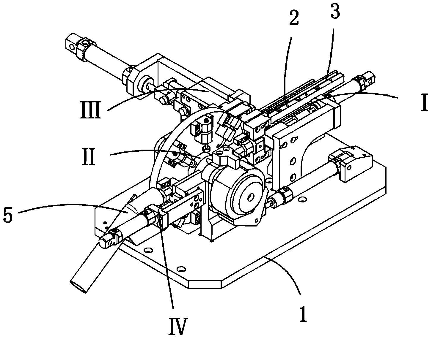
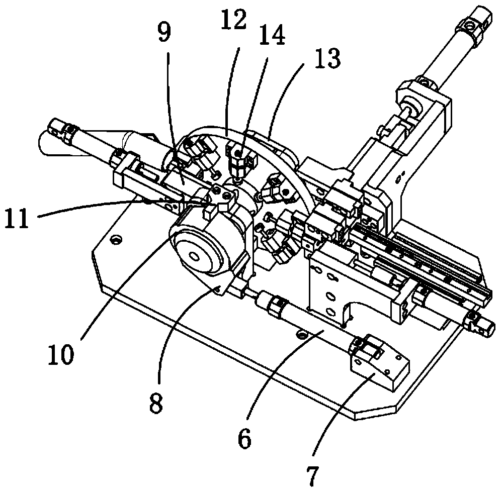
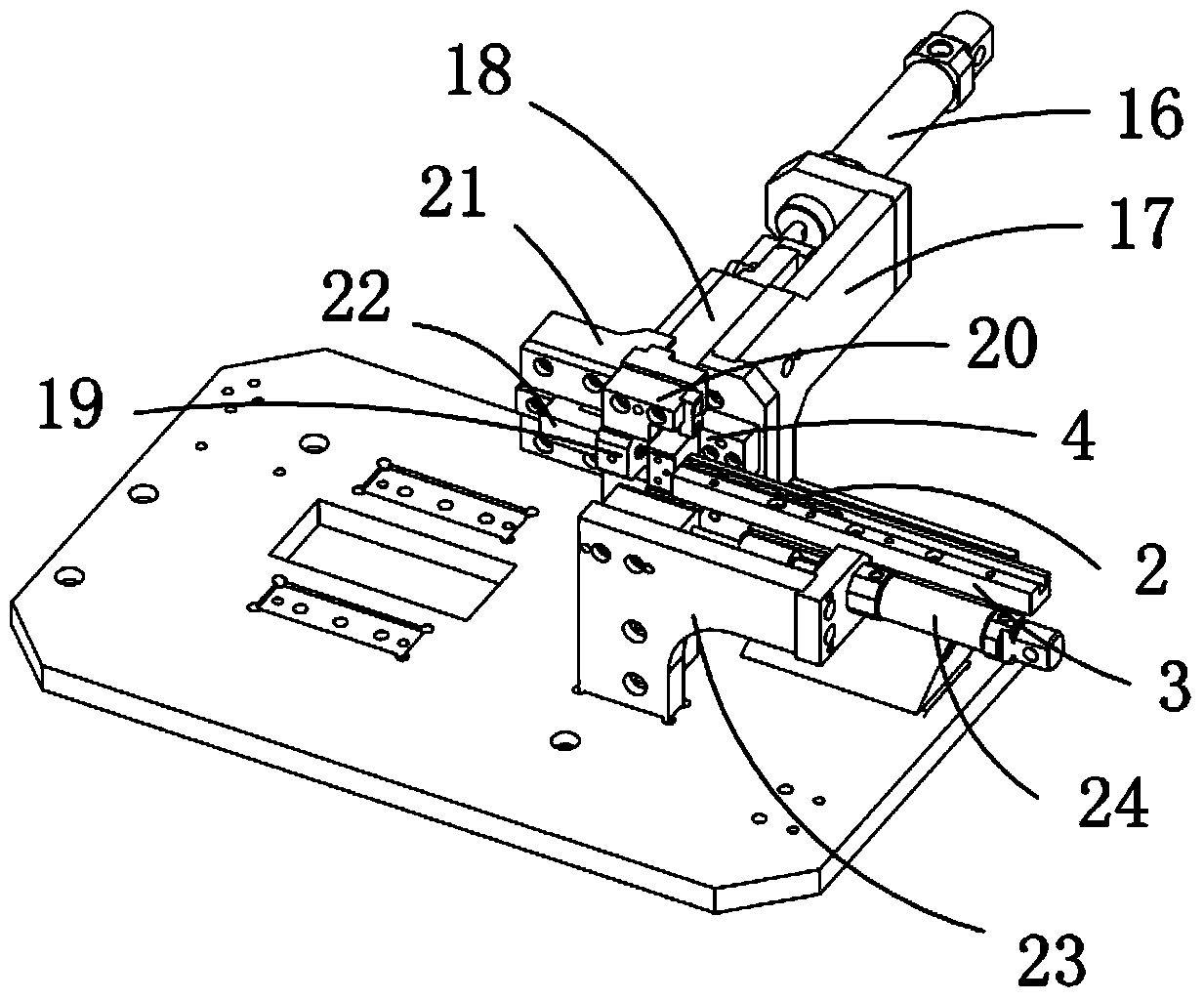
[0027] Examples, see attached Figure 1-9 , a material transportation mechanism, which includes a base 1, a material 2, a material tank 3, a feeding rail connection block 4, a material outlet pipe 5, a feeding mechanism I, a turntable mechanism II, a pushing mechanism III and a lifting mechanism IV, the The material tank and the material outlet pipe are respectively installed on the base, the material is located in the material tank, and the feeding rail connection block is located at the front end of the material tank; the turntable mechanism includes a turntable drive cylinder 6, a turntable drive cylinder fixing seat 7, a one-way Swing block 8, turntable fixing seat 9, turntable 10, block 11, disc 12, disc fixing seat 13 and product fixing seat 14, described turntable driving cylinder fixing seat is fixed on the base, and the rear end of turntable driving cylinder is connected to On the fixed seat of the turntable drive cylinder, the front end of the turntable drive cylinde...


PUM


Abstract

The invention relates to a material conveying mechanism. Materials are fed from a material groove, then reach the position of a feeding guide rail connecting block and enter a receiving block, an inductor induces whether the materials exit or not, after the materials enter the receiving block, a material pushing air cylinder drives a sliding block to forwards move to push the connecting block to enable the receiving block to forwards move with the materials, the materials are moved to the position aligned with a product fixing base, and then the material feeding air cylinder drives a feeding rod to push the materials to the product fixing base from the receiving block; a rotary disc driving air cylinder drives a rotary disc to rotate to drive a disc to rotate, the disc can only perform one-way rotation under the effect of a one-way swinging block, the product fixing base can be aligned with the receiving block one time when the disc rotates once, and therefore continuous material feeding is achieved; when the materials rotate in the product fixing base to be at the vertical position, the tapping process is carried out, after tapping is finished, the disc continuously rotates, when the materials are aligned with a material outlet pipe, a material ejecting air cylinder in a material ejecting mechanism drives a brake block to push an ejecting block to eject out the completely-machined materials from the product fixing base, and the completely-machined materials are taken out form the material outlet pipe.

Description

Technical field: [0001] The invention relates to the field of material transport mechanism equipment, and more specifically relates to a material transport mechanism for automatically providing materials in the process of teeth flushing. Background technique: [0002] In the process of material punching, the material needs to be transported to the standard operating position for the punching work. The existing material transportation mechanism is generally operated manually, and its work efficiency is low, and the punching position is not accurate, which affects the product quality. Invention content: [0003] The purpose of the present invention is to provide a material transport mechanism for the deficiencies of the prior art, which is used to automatically provide materials during the punching process, and the punching is accurate. At the same time, the cost of the cylinder is low, the use of motors is reduced, and the cost is reduced. [0004] Technical solutions of th...

Claims


Application Information

Patent Timeline
IPC IPC(8): B65G47/04B65G29/00B65G47/82B65G43/08
Inventor 吕绍林杨愉强吴小平肖坡曹德基
Owner BOZHON PRECISION IND TECH CO LTD
Why Eureka
Try Eureka