Supercharge Your Innovation With Domain-Expert AI Agents!

Deflecting bit

A drill bit and deflecting technology, which is applied to drill bits, drilling equipment, earth-moving drilling, etc., can solve problems such as easy blockage of drill bit water holes, and achieve the effects of reducing accidents in holes, avoiding water hole blockage, and preventing accumulation.

Active Publication Date: 2014-03-19
CHINA SHENHUA ENERGY CO LTD +1
View PDF5 Cites 0 Cited by
  • Summary
  • Abstract
  • Description
  • Claims
  • Application Information

AI Technical Summary

Problems solved by technology

[0003] The present invention aims to provide a deflection drill bit to solve the problem of easy blockage of the water hole of the drill bit in the prior art

Method used


Image

  • Deflecting bit
  • Deflecting bit

Examples


Embodiment Construction

[0020] It should be noted that, in the case of no conflict, the embodiments in the present application and the features in the embodiments can be combined with each other. The present invention will be described in detail below with reference to the accompanying drawings and examples.

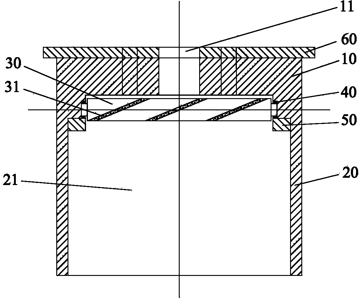
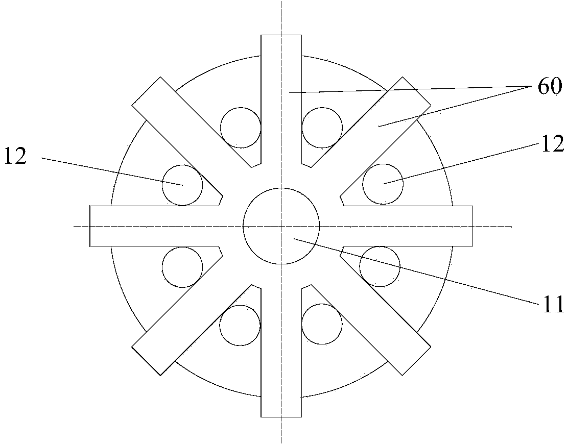
[0021] Such as figure 1 As shown, the deflection drill bit of the present embodiment includes a water hole section 10, a flow section 20 and a rotating shaft 30, the water hole section 10 has a water hole, the flow section 20 has a flow hole 21, and the water hole has a first end and a second end. Two ends, the second end of the water eye communicates with the flow hole 21 , and the rotating shaft 30 is rotatably arranged in the flow hole 21 .

[0022] Applying the deflection drill bit of this embodiment, a rotating shaft 30 is provided in the flow hole 21 . When carrying out directional drilling, mud enters in the water eye, utilizes the power of mud to promote rotating shaft 30 to rotate, a...


PUM


Abstract

The invention provides a deflecting bit. The deflecting bit comprises a water hole section (10) and a flowing section (20). The water hole section (10) is provided with a water hole and the flowing section (20) is provided with a flowing hole (21). The water hole is provided with a first end and a second end communicated with the flowing hole (21). The deflecting bit further comprises a rotating shaft (30) rotably arranged in the flowing hole (21). The deflecting bit effectively solves the problem that a bit water hole can be easily blocked in the prior art.

Description

technical field [0001] The invention relates to the technical field of petroleum drilling engineering, in particular to a deflecting drill bit. Background technique [0002] At present, when mineral exploration uses directional deflection drill bits for drilling, since the directional deflection drill bits used all have a central dead point, the rock ore core at the central dead point cannot be broken. Drilling for a long time will produce many small cores in the directional build bit. Excessive small cores increase mud circulation pressure and change drilling fluid parameters. Due to the existence of the central dead point, it also affects the success of directional build-up. Excessive cores require frequent lifting of the drill bit. At the same time, too many cores will block the water hole of the drill bit, making it difficult to clean the bottom of the well and prone to in-hole accidents such as burning drills. Contents of the invention [0003] The present inventio...

Claims


Application Information

Patent Timeline
Patent Type & Authority Applications(China)
IPC IPC(8): E21B7/08E21B10/42
Inventor 向军文张磊许嘉珊陈艳娜宋扬
Owner CHINA SHENHUA ENERGY CO LTD
Features
  • R&D
  • Intellectual Property
  • Life Sciences
  • Materials
  • Tech Scout
  • Unparalleled Data Quality
  • Higher Quality Content
  • 60% Fewer Hallucinations
Learn More