
Press activating structure

A multi-directional key, touch pressure technology, applied in emergency actuators, electrical components, electrical switches, etc., can solve problems such as mis-pressing, the proximity of multiple touch buttons, and difficulty.

Inactive Publication Date: 2014-03-19
潘建全
View PDF4 Cites 2 Cited by
  • Summary
  • Abstract
  • Description
  • Claims
  • Application Information

AI Technical Summary

Problems solved by technology

However, with the miniaturization and miniaturization of electronic products, the touch buttons are also getting smaller, and the distance between multiple buttons is also getting closer. Therefore, it is very easy to cause the user to press the button with his finger and press multiple buttons at the same time. Inadvertent pressing of a button
Moreover, for buttons with smaller size and spacing, it will be difficult to prevent linkage and accidental touches between different buttons in terms of structural design.

Method used


Image

  • Press activating structure
  • Press activating structure
  • Press activating structure

Examples


Embodiment Construction

[0030] The technical means adopted by the present invention to achieve the predetermined purpose of the invention are further described below with reference to the drawings and preferred embodiments of the present invention.

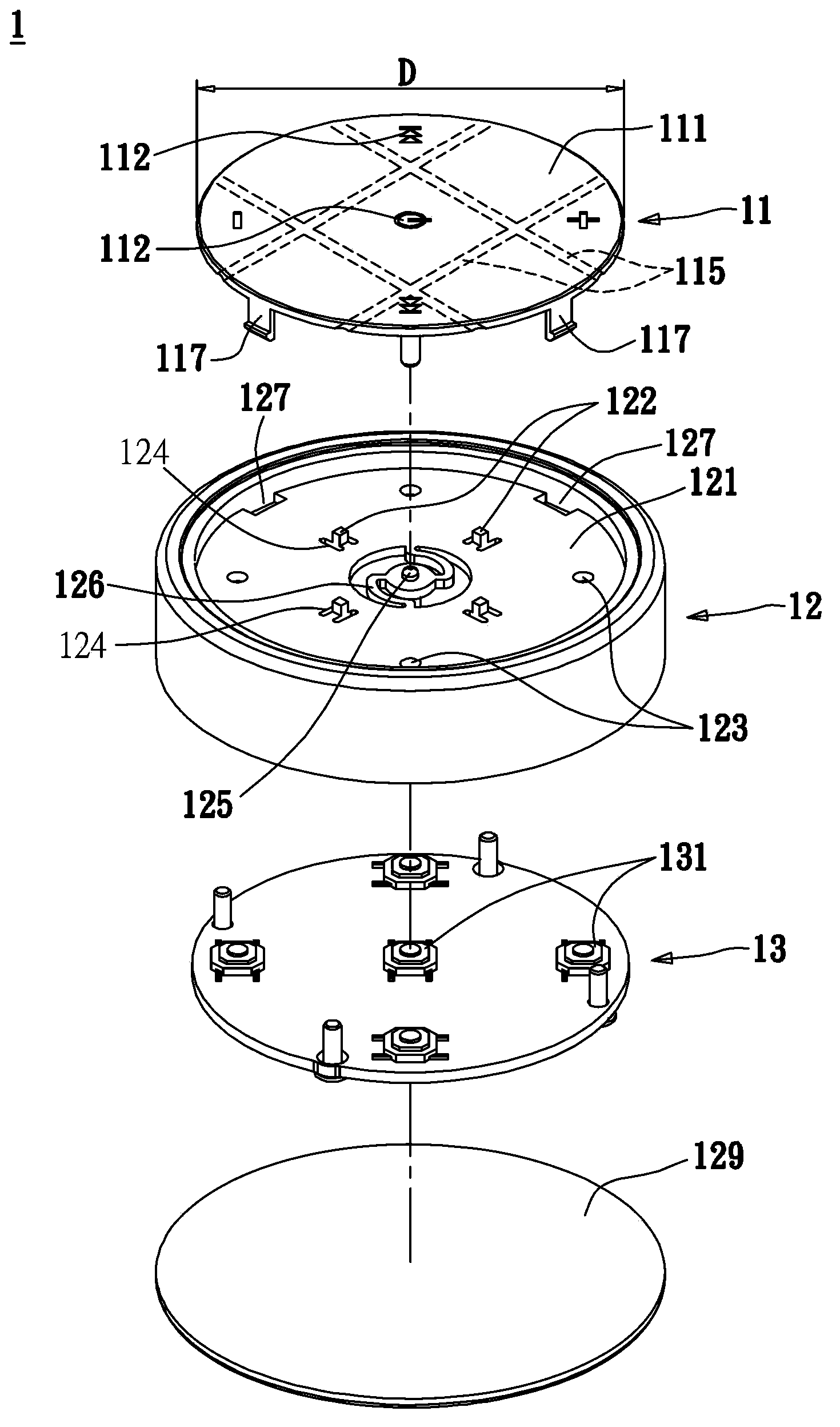
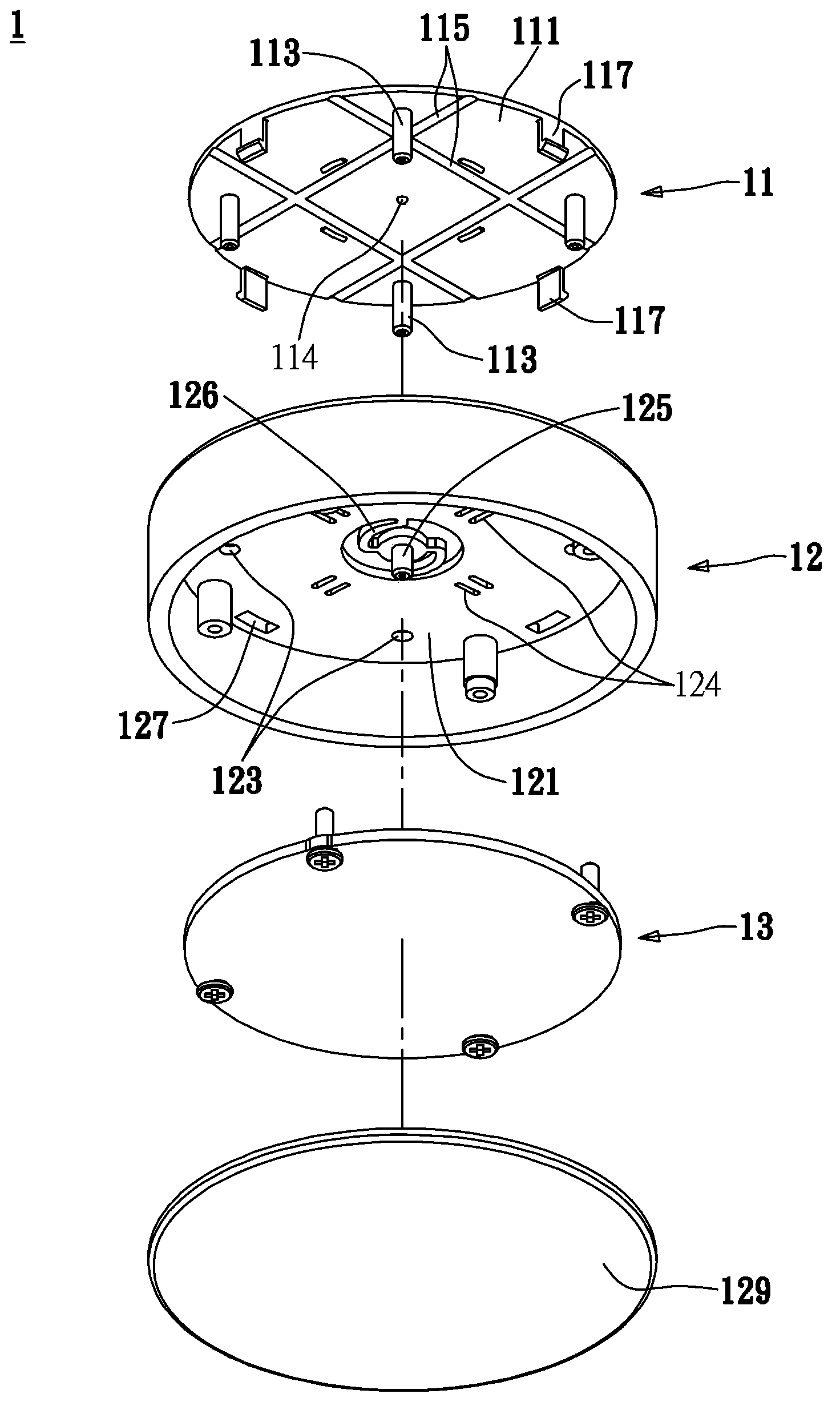
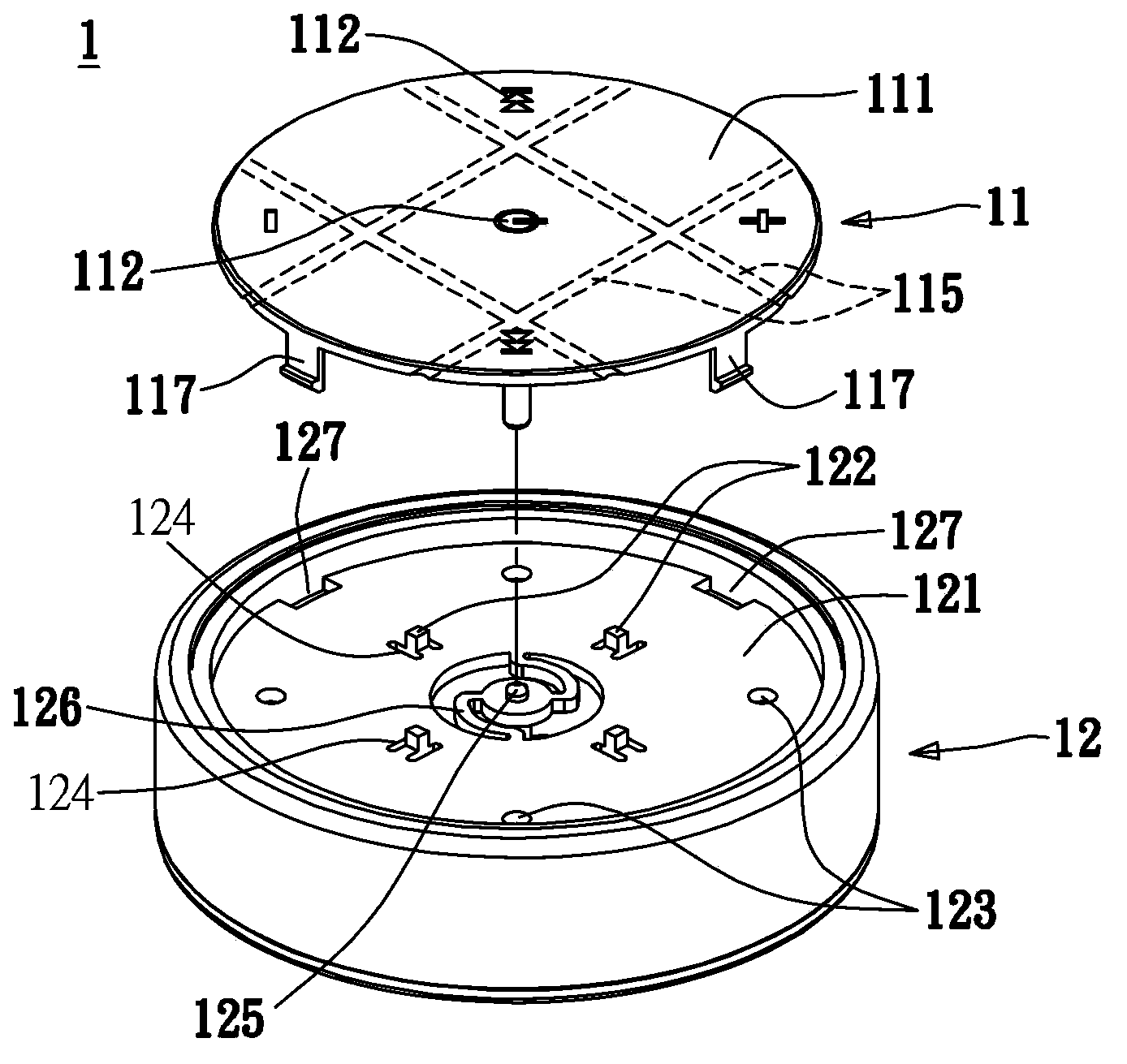
[0031] see also Figure 1A , Figure 1B and Figure 4 , Figure 1A and Figure 1B Shown is an exploded schematic diagram of the multi-directional key press trigger structure of the present invention, Figure 4 Shown is a cross-sectional view of the multi-directional key pressing trigger structure of the present invention. As shown in the figure, the multi-directional key press trigger structure 1 of the present invention is installed and arranged on an electronic product (not shown), and the purpose is to use the multi-directional key press trigger structure 1 to operate and control the electronic product. Software and hardware functions. Generally speaking, the electronic product is preferably a mobile phone, a smart phone, a personal digital assist...


PUM


Abstract

The present invention relates to a press activating structure for assembling in an electrical product and controlling the electrical product. The press activating structure comprises a button unit, a circuit board and a casing. The button unit has a flexible first plate, at least one dividing trough, a plurality of pressing sites and first contact element, where the dividing trough isolates the first contact elements, and each pressing site corresponds to and simultaneously moved with a first contact element. The circuit board has a plurality of signal generations, where each signal generation is adjacent to a first contact element. The casing has a plurality of dividing elements, whose ends are adjacent to the first plate, to break the first plate into several distinct regions.

Description

technical field [0001] The invention relates to a multi-directional key pressing trigger structure, in particular to a multi-directional key pressing trigger structure which can prevent mis-pressing and is used for any electronic instrument. Background technique [0002] With the advancement of science and technology, human beings have used a large number of electronic technologies to improve people's lives. Whether it is work, entertainment, or factory monitoring, you can see the use of these electronic technology products. For example, people have become accustomed to portable devices such as mobile phones, smart phones, personal digital assistants (PDAs), notebook computers, MP3 players, pen drives, iPads, iPods, iPhones, e-books, etc. electronic products to meet the basic needs of daily life. These electronic technology products have gradually become indispensable daily necessities for people due to their light, thin and short characteristics. With the evolution of hu...

Claims


Application Information

Patent Timeline
Patent Type & Authority Applications(China)
IPC IPC(8): H01H25/00
CPCH01H13/64H01H2221/052H01H13/7057H01H2221/054H01H2221/05H01H25/041
Inventor 潘建全
Owner 潘建全
Learn More