Piston for an internal combustion engine

A technology for internal combustion engines and pistons, applied to pistons, mechanical equipment, engine components, etc., can solve problems such as insufficient cooling, and achieve the effect of ensuring axial positioning in a simple way

Active Publication Date: 2014-03-19
MAHLE INT GMBH
View PDF4 Cites 2 Cited by
  • Summary
  • Abstract
  • Description
  • Claims
  • Application Information

AI Technical Summary

Problems solved by technology

The problem with this method is that the cooling oil is only injected point by point into the cooling channels, resulting in areas in the piston that are not sufficiently cooled

Method used


Image

  • Piston for an internal combustion engine
  • Piston for an internal combustion engine
  • Piston for an internal combustion engine

Examples


Embodiment Construction

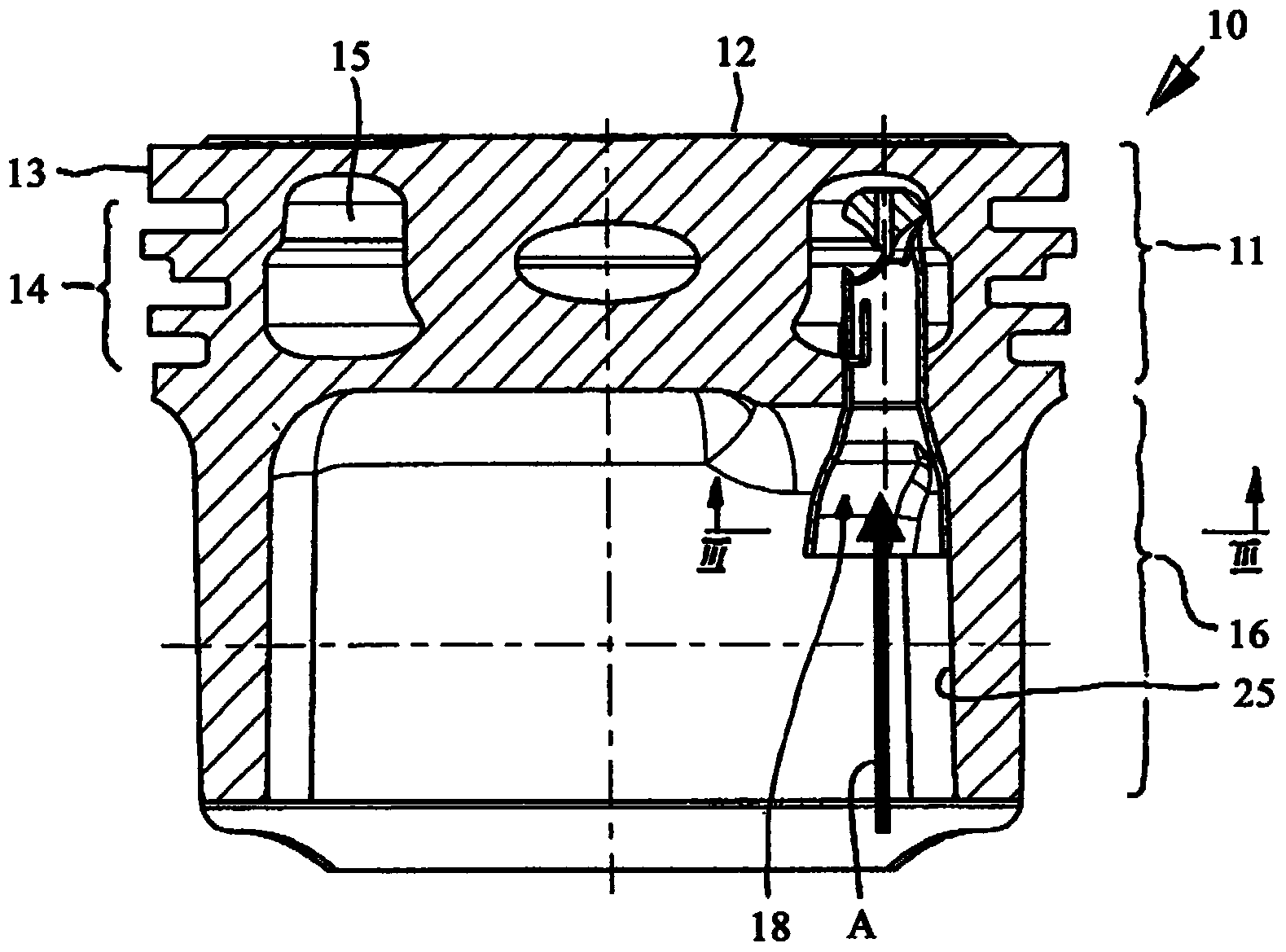
[0020] exist Figures 1 to 3 A piston 10 according to the invention for an internal combustion engine is shown by way of example. The one-piece piston 10 in the exemplary embodiment has a piston head 11 with a piston crown 12 which can be provided in a known manner with a piston crown pocket (not shown in the figures). An annular fire land 13 and an annular piston ring band 14 having an annular groove are connected to the piston top 12 , and the annular groove is used to accommodate a piston ring (not shown in the figure). An annular cooling channel 15 is provided in the region of the piston ring band 14 . In addition, the piston 10 also has a piston skirt 16 in a known manner.

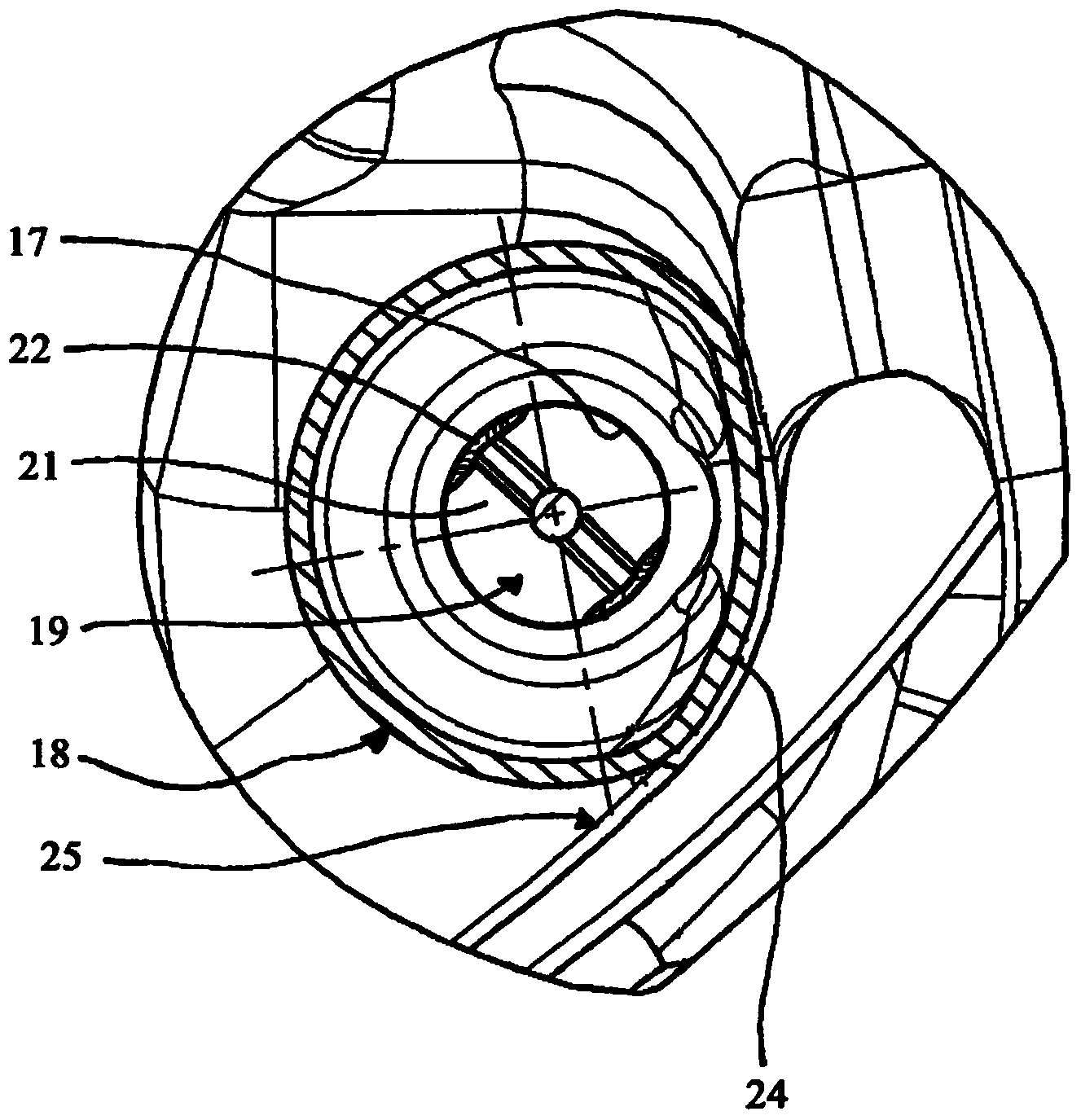
[0021] The piston 10 operates in a block crankcase, which is provided in a known manner with nozzles, by means of which the cooling oil fluid A is injected into a bore hole 17 , which in the exemplary embodiment is of substantially cylindrical design . The bore 17 opens into the cooling channel 15...


PUM


Abstract

The present invention relates to a piston (10) for an internal combustion engine, comprising a piston head (11) and a piston skirt (16), with a cooling channel (15) arranged in the piston head (11) and with at least one bore (17) opening into the cooling channel (15), a conduit (18) for a cooling oil jet (A) being housed in said bore. According to the invention, a jet divider (19) is arranged at the first free end (18a) of the conduit (18) and, in the area of the second free end (18b) of the conduit (18), the outer lateral surface of conduit (18) has a contact surface (24) that lies, secured against torsion, against an inner surface (25) of the piston (10).

Description

technical field [0001] The invention relates to a piston for an internal combustion engine, comprising a piston head and a piston skirt, a cooling channel in the piston head and at least one bore opening into the cooling channel, in which a conduit for cooling oil fluid is accommodated drilling. Background technique [0002] For example, WO 00 / 04286 A1 discloses a piston having a cooling channel into which a conduit for cooling oil fluid is accommodated. The cooling oil circulating in the cooling passage is used to cool the piston. In a known manner, cooling oil is injected into at least one inlet port, usually by means of at least one piston nozzle located in the region of the crankcase. The problem with this method is that the cooling oil is only injected point-by-point into the cooling channels, so that parts of the piston are not sufficiently cooled. SUMMARY OF THE INVENTION [0003] The object of the present invention is to improve such a piston in order to achieve...

Claims


Application Information

Patent Timeline
IPC IPC(8): F02F3/22
CPCF02F3/22
Inventor 马库斯·莱特尔
Owner MAHLE INT GMBH
Why Eureka
Try Eureka