Eureka AIR delivers breakthrough ideas for toughest innovation challenges, trusted by R&D personnel around the world.

Sealing device and damper with sealing device

A sealing device and dust-proof sealing technology, which is applied to the sealing of engines, shock absorbers, shock absorbers, etc., and can solve problems such as working fluid leakage, user discomfort, and leakage

Inactive Publication Date: 2014-03-19
KYB CORP
View PDF8 Cites 0 Cited by
  • Summary
  • Abstract
  • Description
  • Claims
  • Application Information

AI Technical Summary

Problems solved by technology

[0014] However, since the flange shape of the dust-proof sealing flange 300 is set so that the working fluid film thickness during the compression process when the piston rod 2 enters the cylinder body 1 is thinner than the working fluid film thickness during the stretching process when the piston rod 2 withdraws from the cylinder body 1 Therefore, the working fluid in the space 8 may be gradually released to the outside side (atmosphere side), causing the working fluid to leak and causing discomfort to the user.
[0015] In addition, the leakage of the working fluid in this case occurs only when the vehicle is suddenly started after being left for a long time. Since the amount of the leaked working fluid is extremely small, it is different from the case where there is a scratch on the outer periphery of the piston rod 2. resulting progressive working fluid leakage

Method used


Image

  • Sealing device and damper with sealing device
  • Sealing device and damper with sealing device
  • Sealing device and damper with sealing device

Examples


Embodiment Construction

[0027] Hereinafter, embodiments of the present invention will be described with reference to the accompanying drawings. The same reference numerals used in some of the figures denote the same or corresponding parts.

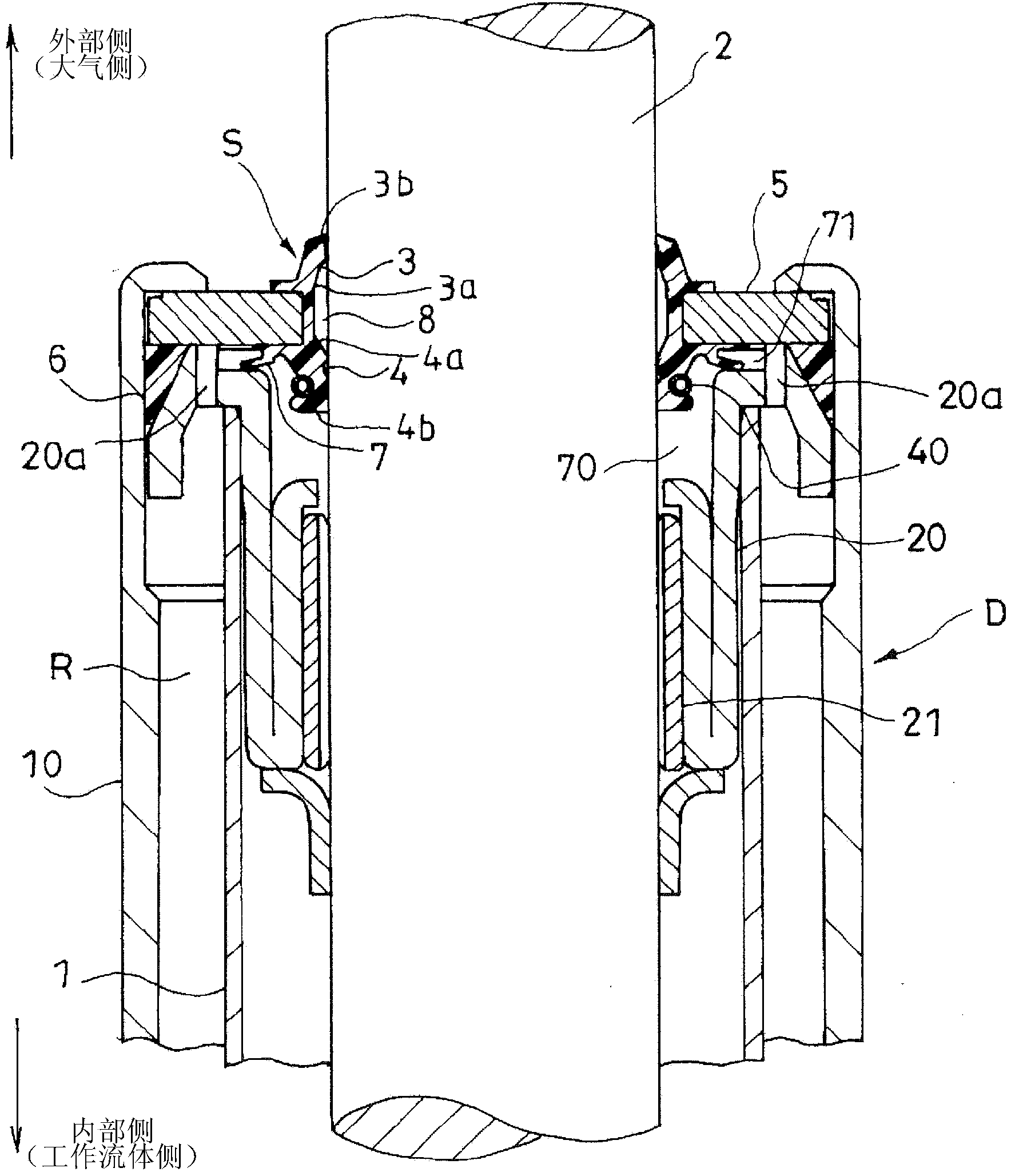
[0028] like figure 1 As shown, a sealing device S is used to seal the outer periphery of a piston rod (shaft member) 2 movably inserted into a cylinder (cylinder member) 1 for accommodating a working fluid. The sealing device S includes: a dust seal flange 3 arranged on the outer side (atmosphere side) of the cylinder block 1 to prevent the intrusion of foreign matter; and an oil seal flange 4 arranged on the inner side (working fluid side) of the cylinder block 1 side) and is used to prevent the outflow of working fluid. A space in which the working fluid resides is formed between the dust seal flange 3 and the oil seal flange 4 .

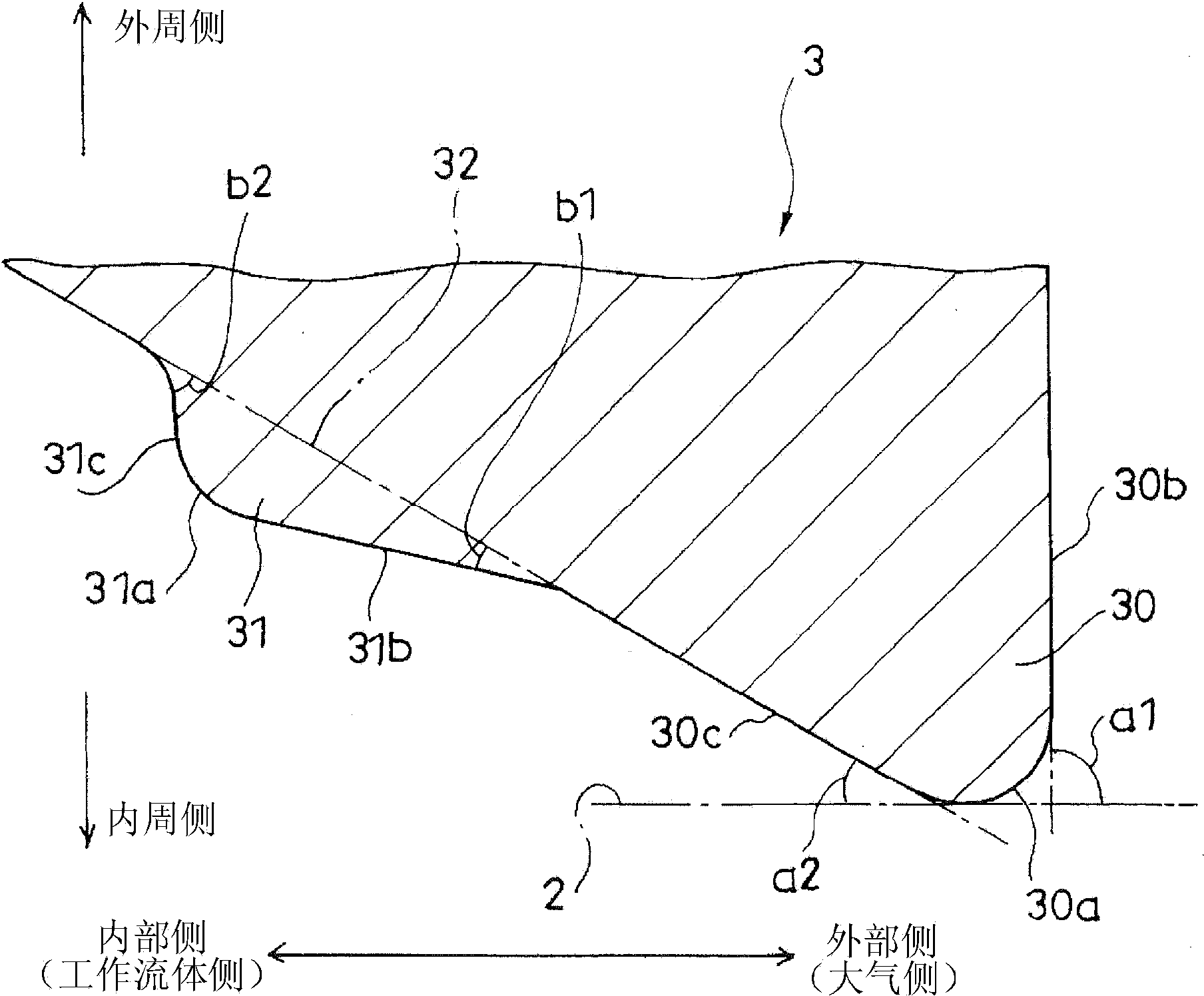
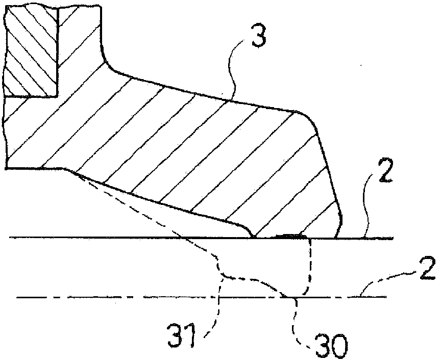
[0029] like figure 2 As shown, the dust seal flange 3 includes a main flange portion 30 and a sub flange portion 31 formed at...


PUM


Abstract

A sealing device for sealing the outer periphery of a shaft member inserted in a tube member is provided with: a dust seal lip disposed on the outside of the tube member; and an oil seal lip disposed on the inside of the tube member and forming a space between the oil seal lip and the dust seal lip, the space retaining working fluid. The dust seal lip has a main lip and a sub-lip which is formed closer to the oil seal lip than the main lip. The highest of the absolute values of surface pressure gradients on the inside of the sub-lip is set to be greater than the highest of the absolute values of surface pressure gradients on the outside of the sub-lip.

Description

technical field [0001] The present invention relates to an improvement in a sealing device and a damper provided with the sealing device. Background technique [0002] The sealing device is applied to a shock absorber for suppressing vibration of conveying equipment and buildings, a cylinder device for hydraulic drive, and the like, and is used to seal the working fluid contained in the shock absorber, the cylinder device, and the like. [0003] For example, JP2006-17161A discloses a sealing device which is applied to a shock absorber for suspension, which is installed between the vehicle body and the wheel of an automobile and is used for suppressing road surface unevenness caused by unevenness. Vibration is transmitted to the body. [0004] like Figure 4 As shown, the above-described sealing device S1 is used to seal the outer periphery of the piston rod (shaft member) 2 movably inserted into the cylinder (cylinder member) 1 of the shock absorber D. As shown in FIG. The...

Claims


Application Information

Patent Timeline
Patent Type & Authority Applications(China)
IPC IPC(8): F16J15/32F16F9/36F16F9/32F16C33/72
CPCF16J15/3236F16F9/36F16J15/32F16J15/56
Inventor 尾崎慎次斋田周作伊藤清明井元智可至
Owner KYB CORP
Why Eureka
Eureka Blog
Learn More