
Magnetic Therapy Machine

A treatment machine and treatment bed technology, which is applied in the field of magnetic coupling treatment equipment, can solve the problems of small on-site assembly operation space, inconvenient installation and maintenance, and no protection measures, and achieves short installation time, convenient processing and good treatment effect. Effect

Inactive Publication Date: 2015-09-30
SHANDONG HEXIER MEDICAL EQUIP
View PDF11 Cites 0 Cited by
  • Summary
  • Abstract
  • Description
  • Claims
  • Application Information

AI Technical Summary

Problems solved by technology

[0003] 1. Inconvenient installation and maintenance: the existing large-scale equipment is assembled at the use site for the convenience of transportation. The upper end of the seat is integrally equipped with a flange. When installing, first install the bearing seat on the frame from top to bottom, and install the rotating shaft into the bearing seat from bottom to top. At this time, multiple bearings need to be installed between the rotating shaft and the bearing seat. The assembly operation space is small, and it takes a long time to lift the upper turntable and the rotating shaft with lifting equipment, which makes the installation difficult, and requires a lot of installation workers, which increases the cost and the maintenance cost will be very high
[0004] 2. The reliability is poor. The gyromagnetic treatment machine needs to fix a lot of magnetic blocks on the upper and lower heads, and high-speed rotation can achieve the ideal therapeutic effect. The weight of the upper head can reach 200 kg. The existing gyromagnetic There are not enough protective measures for the treatment machine. Once the bearing fails and the head falls, it will cause very serious consequences.

Method used


Image

  • Magnetic Therapy Machine
  • Magnetic Therapy Machine
  • Magnetic Therapy Machine

Examples


Embodiment Construction

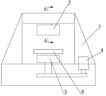
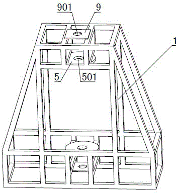
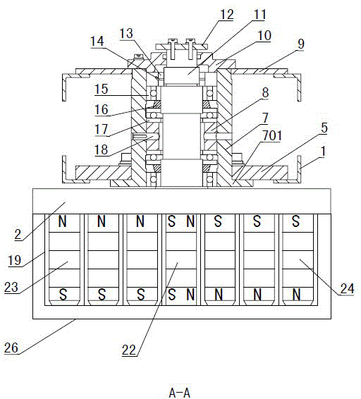
[0037] Figure 1~13 It is the best embodiment of the gyromagnetic therapy machine of the present invention, below in conjunction with the attached Figure 1~13 The present invention will be further described.

[0038] Refer to attached figure 1 : Gyromagnetic treatment machine, including a frame 1, an upper rotary table 2 and a lower rotary table 3, the upper rotary table 2 is installed on the upper part of the frame 1 for rotation, the lower rotary table 3 is coaxially rotated and installed at the lower part of the frame 1, the upper rotary table 2 and the lower rotary table 3 Magnetic blocks with opposite polarities are fixed on the opposite surfaces. A treatment couch 6 is fixed between the upper turntable 2 and the lower turntable 3. The treatment couch 6 can slide back and forth. The lower turntable 3 is connected to the motor 4 through a belt, and the motor 4 drives the The turntable 3 rotates, the lower turntable 3 is magnetically coupled with the magnetic block on th...


PUM


Abstract

The invention discloses a gyromagnetic therapy machine, and belongs to the field of medical equipment. Magnets with opposite polarities are fixed on opposite surfaces of an upper turn plate (2) and a lower turn plate (3), the lower turn plate (3) is connected with a motor (4), the motor (4) and a therapy bed (6) are connected with a control circuit, and the upper turn plate (2) is fixed in a bearing block (7) through the rotation of a rotation shaft (11) on the upper side of the upper turn plate (2). The gyromagnetic therapy machine is characterized in that the upper part of a rack (1) is provided with an upper fixing plate (9) and a lower fixing plate (5), a lower fixing hole (501) is formed in the middle part of the lower fixing plate (5), the lower end of the bearing block (7) is integrally provided with a flange (701), the flange (701) is fixed on the lower end face of the lower fixing plate (5), the upper end of the bearing block (7) is fixedly connected with the upper fixing plate (9) after passing through the lower fixing hole (501), and the bearing block (7) and the upper turn plate (2) are integrally arranged on the rack (1) from bottom up. The gyromagnetic therapy machine has the advantages of convenience to install, simple structure, reliable operation and the like.

Description

technical field [0001] A gyromagnetic treatment machine belongs to the field of medical equipment, and specifically relates to a magnetic coupling treatment equipment for treating various diseases such as cancer and improving human immunity. Background technique [0002] Years of clinical trials have confirmed that the use of magnetic fields has outstanding curative effects in the treatment of cancer and other diseases, and a gyromagnetic therapy machine has been developed. Synchronous rotation, through the continuous change of the magnetic field, the cells are vibrated, thereby improving cell activity, improving human immunity, and inhibiting the growth of cancer cells. The current gyromagnetic therapy machine is still in the research and development stage, and has the following defects: [0003] 1. Inconvenient installation and maintenance: the existing large-scale equipment is assembled at the use site for the convenience of transportation. The upper end of the seat is i...

Claims


Application Information

Patent Timeline
Patent Type & Authority Patents(China)
IPC IPC(8): A61N2/12
Inventor 李学超张经家
Owner SHANDONG HEXIER MEDICAL EQUIP
Learn More