Seam welding robot
A technology of robots and robot arms, applied in the field of seam welding robots, can solve the problems of complicated robot motion control and so on
- Summary
- Abstract
- Description
- Claims
- Application Information
AI Technical Summary
Problems solved by technology
Method used
Image
Examples
no. 1 approach )
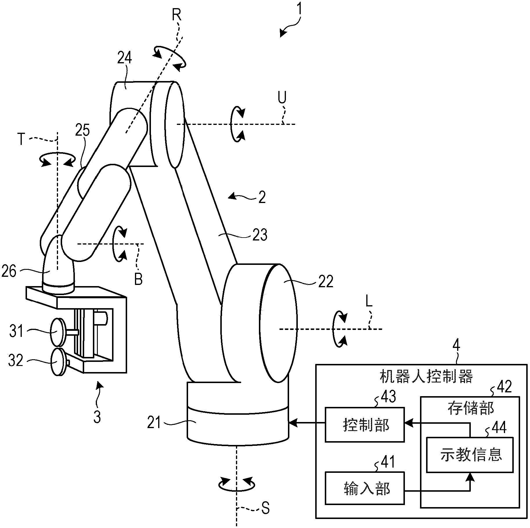
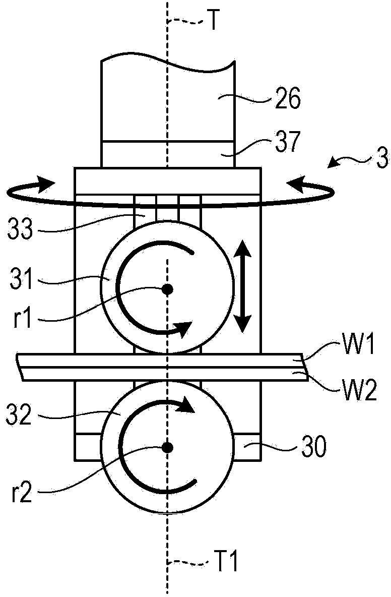
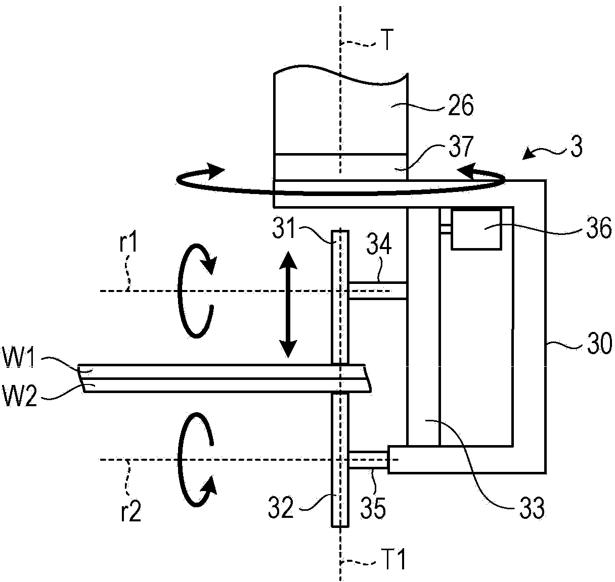
[0023] figure 1 It is a perspective schematic explanatory drawing which shows the seam welding robot 1 which concerns on 1st Embodiment. Such as figure 1 As shown, the seam welding robot 1 includes a robot arm 2 , a welding unit 3 and a robot controller 4 . The welding part 3 is connected to the front end side of the robot arm 2 . The welding part 3 performs seam welding on the object to be welded (object to be welded).
[0024] Although in figure 1 It is omitted in , but the seam welding robot 1 also includes a welding power source for supplying welding current to the welding part 3 . In addition to the welding unit 3 , the welding power source is also connected to the robot controller 4 . When performing seam welding, the welding power source supplies welding current to the welding part 3 according to an instruction from the robot controller 4 . This welding current is supplied based on welding conditions previously set and stored in the welding power source.
[0025]...
no. 2 approach )
[0070] Next, refer to Image 6 and Figure 7 A seam welding robot 1a according to a second embodiment will be described. In this embodiment, for Image 6 and Figure 7 Among the components shown in the image 3 or Figure 5 Constituents that are the same as those shown are given the same image 3 or Figure 5 The symbols shown are the same symbols, and descriptions thereof are omitted.
[0071] Image 6 It is a schematic explanatory drawing which shows the front-end|tip part of the robot arm 2 in the seam welding robot 1a of 2nd Embodiment. also, Image 6 The side surface of the welding part 3 viewed from the rear in the welding advancing direction is schematically shown. Figure 7 It is a top schematic explanatory drawing which shows the operation|movement of the seam welding robot 1a of 2nd Embodiment.
[0072] Such as Image 6As shown, the seam welding robot 1a of the second embodiment includes a welding unit 3 almost the same as that of the first embodiment. H...
no. 3 approach )
[0082] Below, refer to Figure 8 and Figure 9 A seam welding robot 1b according to a third embodiment will be described. In this embodiment, for Figure 8 and Figure 9 Among the components shown in the figure 2 or Figure 5 Constituents that are the same as those shown are given the same figure 2 or Figure 5 The symbols shown are the same symbols, and descriptions thereof are omitted.
[0083] Figure 8 It is a schematic explanatory drawing which shows the front-end|tip part of the robot arm 2 in the seam welding robot 1b of 3rd Embodiment. also, Figure 8 It schematically shows the front of the welding part 3 viewed from the left side in the welding advancing direction. Figure 9 It is a top schematic explanatory drawing which shows the operation|movement of the seam welding robot 1b of 3rd Embodiment.
[0084] Such as Figure 8 As shown, the seam welding robot 1b of the third embodiment is equipped with the welding part 3 which is almost the same as that of ...
PUM
 Abstract
Description
Claims
Application Information
 - R&D
- Intellectual Property
- Life Sciences
- Materials
- Tech Scout
- Unparalleled Data Quality
- Higher Quality Content
- 60% Fewer Hallucinations
Browse by: Latest US Patents, China's latest patents, Technical Efficacy Thesaurus, Application Domain, Technology Topic, Popular Technical Reports.
© 2025 PatSnap. All rights reserved.Legal|Privacy policy|Modern Slavery Act Transparency Statement|Sitemap|About US| Contact US: help@patsnap.com


