Magnetically positioning and crawling type welding machine for steel structures

A steel structure and welding machine technology, applied in welding equipment, auxiliary welding equipment, welding/cutting auxiliary equipment, etc., can solve problems such as personal safety hazards and manual work

Active Publication Date: 2014-03-26
江苏汉地建设工程有限公司
View PDF5 Cites 2 Cited by
  • Summary
  • Abstract
  • Description
  • Claims
  • Application Information

AI Technical Summary

Problems solved by technology

[0002] At present, high-altitude welding of traditional steel structures requires manual work, which brings safety hazards to personal safety

Method used


Image

  • Magnetically positioning and crawling type welding machine for steel structures

Examples


Embodiment Construction

[0009] The magnetic attraction positioning crawling steel structure welding machine of the present invention will be further described in detail below in conjunction with the accompanying drawings and specific embodiments.

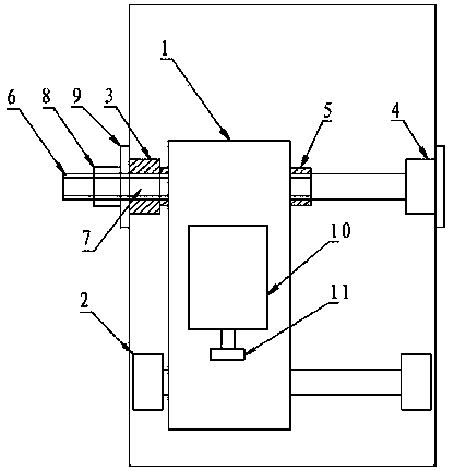
[0010] As shown in the figure, the magnetic suction positioning crawling type steel structure welding machine of the present invention includes a welding torch frame 1 and a frame driving wheel 2. It is characterized in that the axles connecting the left driven wheel 3 and the right driven wheel 4 of the frame are two Section internal and external threaded tubular connection structure, one end of the internal threaded pipe 5 is connected to a left driven wheel 3, one end of the external threaded pipe 6 is connected to the right driven wheel 4, a through hole 7 is set in the center of the left driven wheel 3, and the outer threaded pipe 6 The other end passes through the through hole 7 of the left driven wheel 3, and the externally threaded pipe 6 is fixed i...


PUM


Abstract

The invention comprises a magnetically positioning and crawling type welding machine for steel structures. The magnetically positioning and crawling type welding machine comprises a welding gun frame and frame driving wheels. The magnetically crawling type welding machine is characterized in that an axle connecting a left driven wheel with a right driven wheel of the frame is of a connecting structure of an inner threaded tube and an outer threaded tube; one end of the inner threaded tube is connected with the left driven wheel, and one end of the outer threaded tube is connected with the right driven wheel; a through hole is arranged at the center of the left driven wheel; the other end of the outer threaded tube penetrates the through hole of the left driven wheel; the outer threaded tube is fixed in the inner threaded tube through a locking nut.

Description

technical field [0001] The invention relates to a welding machine, in particular to a magnetic suction positioning crawling type steel structure welding machine. Background technique [0002] At present, high-altitude welding of traditional steel structures requires manual work, which brings potential safety hazards to personal safety. Contents of the invention [0003] The technical problem to be solved by the present invention is to provide a crawling type steel structure welding machine with magnetic suction positioning. [0004] In order to solve the above-mentioned technical problems, a magnetic attraction positioning crawling steel structure welding machine of the present invention includes a welding torch frame and a frame driving wheel, and is characterized in that the wheel shaft connecting the left driven wheel and the right driven wheel of the frame is two sections Internal and external threaded tubular connection structure, one end of the internal threaded ...

Claims


Application Information

Patent Timeline
Patent Type & Authority Applications(China)
IPC IPC(8): B23K37/02
CPCB23K37/0264B23K37/0294B23K2103/04
Inventor 夏致俊
Owner 江苏汉地建设工程有限公司
Why Eureka
Try Eureka