A computer-controlled crawling robot
A crawling robot and computer technology, applied in the field of robotics, can solve problems such as small range and poor practicability, and achieve the effect of improving practicability and crawling stability
- Summary
- Abstract
- Description
- Claims
- Application Information
AI Technical Summary
Problems solved by technology
Method used
Image
Examples
specific Embodiment approach 1
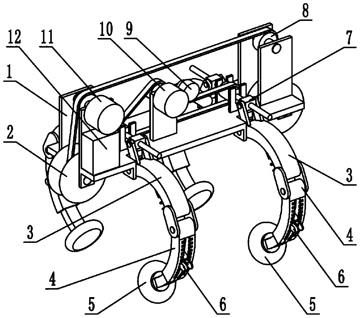
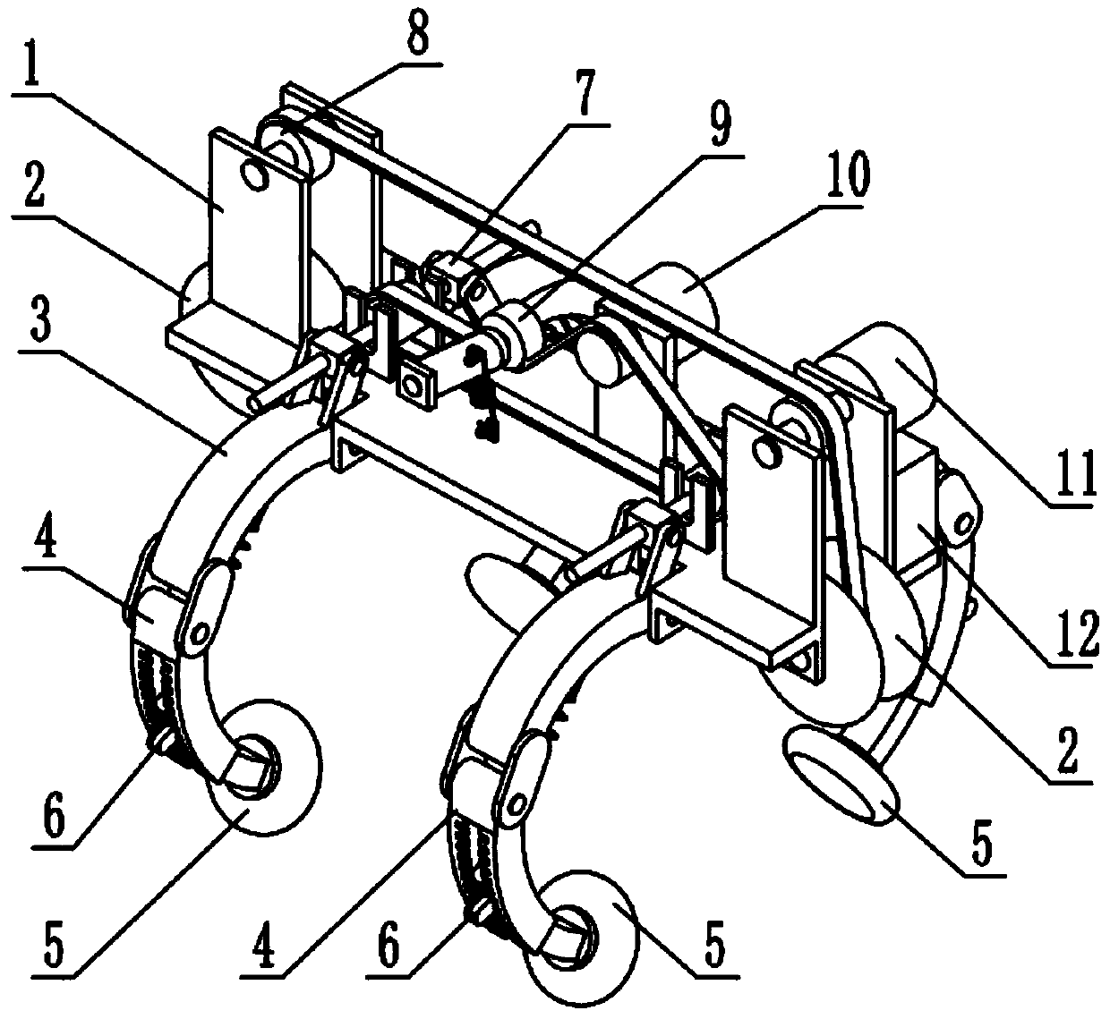
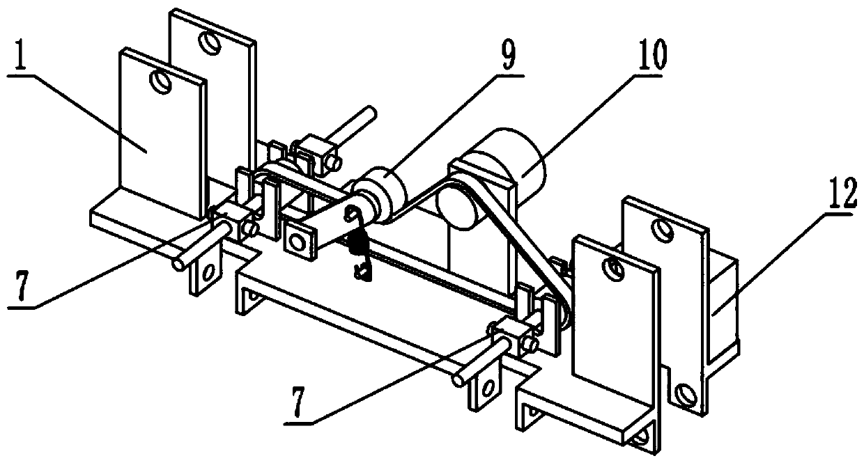
[0033] Such as Figure 1-14 As shown, a computer-controlled crawling robot includes a main frame 1, a crawling wheel 2, a supporting wheel 8, a walking motor 11, and a power supply 12. The crawling wheel 2 is provided with two, and the two crawling wheels 2 are respectively connected to At the front and rear ends of the main frame 1, the supporting wheels 8 are rotatably connected to the rear end of the main frame 1, the walking motor 11 is fixedly connected to the front end of the main frame 1, two crawling wheels 2, supporting wheels 8 and walking The motor 11 is connected by a belt drive, the power supply 12 is fixedly connected to the main frame 1, and the power supply 12 is connected to the walking motor 11 by wires. This computer-controlled crawling robot also includes a rotating crank 3, a clamping crank 4, and a telescopic auxiliary wheel The frame 5, the telescopic locking device 6, the crank angle adjustment mechanism 7, the tensioning mechanism 9 and the adjustment m...
specific Embodiment approach 2
[0036] Such as Figure 1-14 As shown, the main frame 1 includes a crawler wheel seat 1-1, a main board 1-2, a crank arm seat 1-3, a mounting plate 1-4, a hook frame I1-5, a motor mounting plate 1-6 and a limit stop Frame 1-7, the front and rear ends of the main board 1-2 are welded with crawler wheel seats 1-1, four crank arms 1-3 are provided, and the four crank arms 1-3 are all welded to the main board 1-2 , The mounting plate 1-4, the hook frame I1-5 and the motor mounting plate 1-6 are all fixedly connected to the upper end surface of the main board 1-2. There are two limit frames 1-7, two limit frames 1-7 Both are welded on the upper end surface of the main board 1-2, the two crawling wheels 2 are respectively connected to the lower end of the two crawling wheel bases 1-1, and the supporting wheel 8 is connected to the upper end of the rear crawling wheel base 1-1 through a bearing rotation , The walking motor 11 is fixedly connected to the upper end of the front crawler ...
specific Embodiment approach 3
[0039] Such as Figure 1-14 As shown, the crawler wheel 2 includes a walking wheel 2-1, a pulley 2-2, and a rotating shaft 2-3. Both ends of the pulley 2-2 are fixedly connected to the walking wheel 2-1, and the pulley 2-2 is rotatably connected to On the rotating shaft 2-3, the two rotating shafts 2-3 are respectively rotatably connected to the lower ends of the two crawling wheel seats 1-1 through bearings. The output shaft of the walking motor 11 is provided with a transmission pulley, two pulleys 2-2, and a supporting wheel 8. It is connected with the drive pulley on the output shaft of the walking motor 11 through a belt drive;
[0040] The walking motor 11 is powered on by the power supply 12, and the driving pulley on the output shaft of the walking motor 11 drives the pulley 2-2 through a belt, driving the walking wheel 2-1 to rotate, so that the robot moves on the pipeline, two pulleys 2-2 The side-by-side arrangement can increase the stability between the crawling whee...
PUM
 Abstract
Description
Claims
Application Information
 - R&D
- Intellectual Property
- Life Sciences
- Materials
- Tech Scout
- Unparalleled Data Quality
- Higher Quality Content
- 60% Fewer Hallucinations
Browse by: Latest US Patents, China's latest patents, Technical Efficacy Thesaurus, Application Domain, Technology Topic, Popular Technical Reports.
© 2025 PatSnap. All rights reserved.Legal|Privacy policy|Modern Slavery Act Transparency Statement|Sitemap|About US| Contact US: help@patsnap.com


