Cam spring plate mechanism

A technology of cam spring and spring plate, which is applied in the direction of metal processing machinery parts, large fixed members, metal processing, etc., can solve the problems of parts processing deformation, etc., and achieve the effect of easing the action process, good effect, and changing the swing range

Inactive Publication Date: 2014-03-26
CHONGQING BISHAN AIHUA
View PDF0 Cites 0 Cited by
  • Summary
  • Abstract
  • Description
  • Claims
  • Application Information

AI Technical Summary

Problems solved by technology

[0003] The present invention intends to provide a cam spring plate mechanism to solve the problem that the reciprocating mechanism in the prior art easily deforms parts during processing

Method used


Image

  • Cam spring plate mechanism

Examples


Embodiment Construction

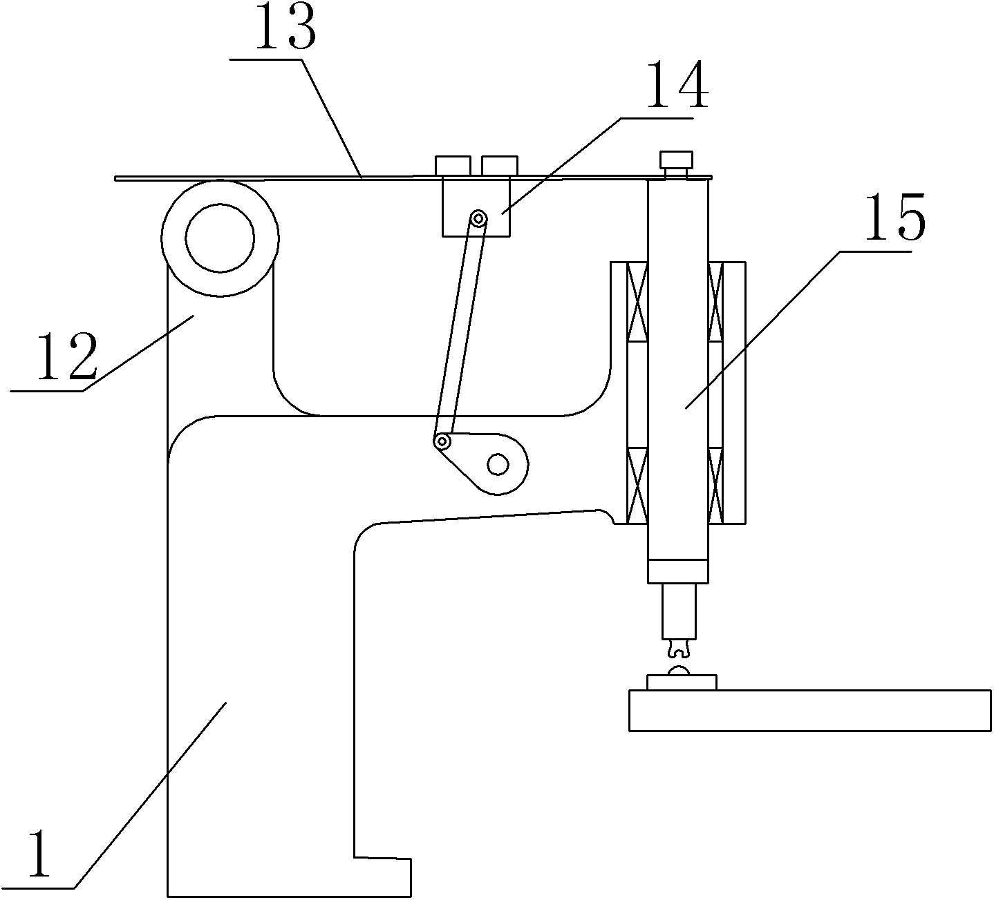
[0009] according to figure 1 As shown, the cam spring plate mechanism in the embodiment of the present invention includes a frame 1, on which a spring plate 13, a clamp seat 12 for clamping the spring plate 13, and a straight rod connected by bolts to one end of the spring plate 13 are arranged on the frame 1 15 and the cam between the clip seat 12 and the straight rod 15, the frame 1 is provided with a sleeve at one end, the straight rod 15 moves axially along the sleeve, the joint between the straight rod 15 and the spring plate 13 is provided with rubber, and includes a clamp Holding the iron block 14, the middle part of the spring plate 13 is fixed to one end of the clamping iron block 14, the other end of the clamping iron block 14 is hinged to one end of the connecting rod, the other end of the connecting rod is hinged to the cam, and the cam rotates on the frame. You can adjust.

[0010] What is described above is only an embodiment of the present invention, and common...


PUM


Abstract

The invention discloses a cam spring plate mechanism which solves the problem that in the prior art, a reciprocating moving mechanism easily deforms a part during machining. The cam spring plate mechanism comprises a machine frame, wherein the machine frame is provided with a spring plate, a clamping base for clamping the spring plate, a straight rod detachably connected with one end of the spring plate and a cam between the clamping base and the straight rod. One end of the machine frame is provided with a sleeve, the straight rod moves axially along the sleeve, the middle of the spring plate is fixed to one end of a clamping iron block, the other end of the clamping iron block is hinged to one end of a connecting rod, the other end of the connecting rod is hinged to the cam, the cam can rotate on the machine frame and the clamping base can be adjusted. The cam spring plate mechanism is simple in structure and good in effect.

Description

technical field [0001] The invention relates to the technical field of reciprocating motion, in particular to a cam spring plate mechanism. Background technique [0002] Reciprocating motion mechanisms are commonly used in machine tools, but most of the existing reciprocating motion mechanisms apply force quickly, which easily leads to deformation of parts. Contents of the invention [0003] The present invention intends to provide a cam spring plate mechanism to solve the problem that the reciprocating mechanism in the prior art easily deforms parts during processing. [0004] The cam spring plate mechanism in this program includes a frame on which a spring plate, a clip seat for clamping the spring plate, a straight rod detachably connected to one end of the spring plate, and a cam located between the clip seat and the straight rod are arranged on the frame. , one end of the frame is provided with a sleeve, the straight rod moves axially along the sleeve, and also inclu...

Claims


Application Information

Patent Timeline
Patent Type & Authority Applications(China)
IPC IPC(8): B23Q1/64B23Q5/00
CPCB23Q5/00
Inventor 袁晴波
Owner CHONGQING BISHAN AIHUA
Why Eureka
Try Eureka