Novel ground condition adaptation type bouncing power leg of hopping robot

An adaptable and robotic technology, applied in the field of jumping robots, can solve the problems of the jumping height of the robot that affects the conversion rate of energy, the power legs cannot touch the ground, and the utilization rate of spring energy is low, and achieves compact structure, convenient control, and high jumping height high effect

Inactive Publication Date: 2014-03-26
SHANGHAI UNIV OF ENG SCI
View PDF5 Cites 6 Cited by
  • Summary
  • Abstract
  • Description
  • Claims
  • Application Information

AI Technical Summary

Problems solved by technology

[0003] In the prior art, a jumping robot that uses energy storage springs as the jumping power, the schematic diagram of its jumping power mechanism is as follows: figure 1 As shown, this kind of mechanism adopts a parallelogram linkage mechanism and a tension spring arranged horizontally. When the tension spring stretches, it stores energy and releases energy when it shrinks. Limited and other disadvantages
Moreover, because the terrain in the working environment of the jumping robot is often very complex, the distance between the power leg of the jumping robot and the ground is often constantly changing, which leads to the fact that when the power leg is in contact with the ground, other supporting legs cannot touch the ground. ; or when other supporting legs are in contact with the ground, the power legs cannot touch the ground, which will greatly affect the energy conversion rate and the jumping height of the robot

Method used


Image

  • Novel ground condition adaptation type bouncing power leg of hopping robot
  • Novel ground condition adaptation type bouncing power leg of hopping robot
  • Novel ground condition adaptation type bouncing power leg of hopping robot

Examples


Embodiment Construction

[0029] The present invention will be further described below in conjunction with the drawings and specific embodiments.

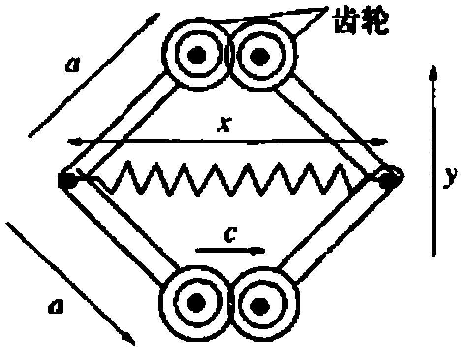
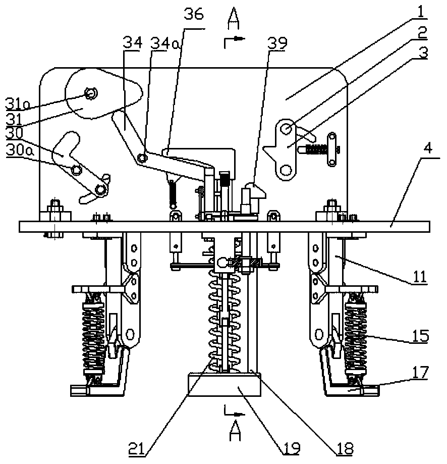
[0030] The bounce power leg of the new terrain adaptive jumping robot mainly includes power spring 21, dead-point push rod guide sleeve, dead-point push rod 48, foot spring 15, kick foot 19, support plate 4, gear a, rack a, Gear b, rack b, parallelogram mechanism 44, etc.

[0031] See Figure 2-9 , A new type of terrain-adaptive jumping robot, including a horizontal support plate 4, below which is fixed 3-4 support legs, the center of the support plate 4 is provided with a bounce leg, the bounce leg includes a kick 19 , The upper part of the pedal 19 is connected with the spring guide post and the tripping rod 18. The spring guide post is sheathed with a power spring 21. The lower end of the power spring presses the pedal 19, and the upper end abuts the support plate 4, and the upper end of the tripping rod 18 is provided with The tripping contact 39, the upper...


PUM


Abstract

The invention relates to a novel ground condition adaptation type bouncing power leg of a hopping robot. The novel ground condition adaptation type bouncing power leg is characterized in that a horizontal supporting plate is included, a bouncing leg is arranged in the centre of the supporting plate and comprises a pedal, the upper portion of the pedal is connected with a spring guide column and a releasing rod, the spring guide column is sleeved with a power spring, the lower end of the power spring presses the pedal, and the upper end of the power spring abuts against the supporting plate. First external power drives the power spring to be compacted and store energy. The upper end of the pedal is respectively hinged to a pair of symmetrical second connecting rods, the upper ends of the second connecting rods are connected with the end portions of a rhomboid connecting rod mechanism through rotating pairs respectively, the rhomboid connecting rod mechanism is fixedly connected with a horizontal gear rack, the gear rack is meshed with a gear, and a gear and gear rack transmission mechanism is formed. The upper ends of the second connecting rods are connected with vertical ejector rods through rotating pairs, the ejector rods are fixedly connected with the supporting plate, the upper ends of the ejector rods are hinged to connecting rods, the connecting rods are hinged to dead point push rods, and the dead point push rods are arranged in vertical dead point push rod guide sleeves in a hollow sleeved mode.

Description

Technical field [0001] The invention relates to a bounce power leg of a jumping robot, in particular to a bounce power leg of a new type of terrain adaptable jumping robot, belonging to the technical field of jumping robots. Background technique [0002] With the increasing application scope of modern robots and the increasingly harsh working environment of robots. Tasks such as archaeological exploration, interstellar exploration, military reconnaissance, and counter-terrorism activities also put forward higher requirements on the performance of robots, which should have strong terrain adaptability and autonomous movement capabilities. Compared with mobile robots that use crawling or crawler motion, jumping robots can easily jump over obstacles or ditches that are several times larger than their own size. It has the characteristics of high mobility, wide range of motion, and strong ability to avoid risks. Suitable for working in complex and unpredictable environments. In the e...

Claims


Application Information

Patent Timeline
Patent Type & Authority Applications(China)
IPC IPC(8): B62D57/028
Inventor 杭鲁滨蔡进卞怀强李文星付志宇许海陆九如丁洪汉李畅王玉昭佳乐
Owner SHANGHAI UNIV OF ENG SCI
Why Eureka
Try Eureka