Lifting roller way machine

A roller table machine and roller table technology, applied in the direction of roller table, conveyor objects, transportation and packaging, can solve the problems of complex chain lifting or lowering mechanism, complex electrical control, inaccurate positioning, etc. Simple electrical control and stable operation

Inactive Publication Date: 2014-03-26
DALIAN JIALIN EQUIP MFG
View PDF8 Cites 3 Cited by
  • Summary
  • Abstract
  • Description
  • Claims
  • Application Information

AI Technical Summary

Problems solved by technology

[0002] At present, the conveying and packaging production lines produced by many conveying and packaging machinery factories at home and abroad mostly use chains to lift or lower the packaging to meet the purpos

Method used


Image

  • Lifting roller way machine
  • Lifting roller way machine
  • Lifting roller way machine

Examples


Example Embodiment

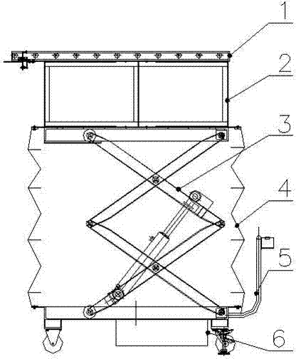
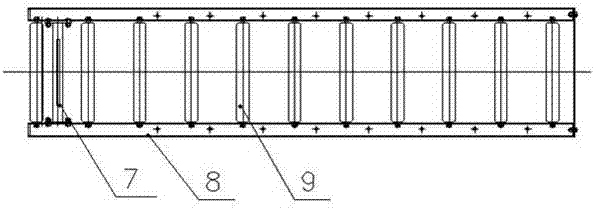
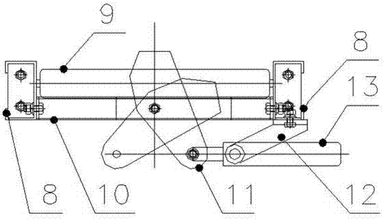
[0022] Such as Figure 1-Figure 7 As shown, the lifting roller table includes a roller table 1, a frame body 2, a four-bar connecting mechanism 3, a protective cover 4, a trolley 5, and a power unit 6. The roller table 1 can be an unpowered roller according to the requirements of use The track can also be a powered roller track. The present invention is an unpowered roller track. The roller track 1 is connected to the four-bar connecting mechanism 3 through the frame 2 and the four-bar connecting mechanism 3 is installed on the trolley 5 to achieve For the purpose of moving the lifting roller conveyor, a power unit 6 is installed at the lower part of the trolley 5. In order to prevent the four-bar connecting mechanism 3 and the power unit 6 from being corroded by water, a protection is provided between the frame 2 and the trolley 5 The cover 4 achieves the purpose of not being corroded by water when cleaning the lifting roller conveyor with water. The protective cover 4 include...


PUM


Abstract

The invention discloses a lifting roller way machine which comprises a roller way, a rack, a four-rod connecting mechanism, a protective cover, a trolley and a power unit. The roller way is connected with the four-rod connecting mechanism through the rack, the four-rod connecting mechanism is installed on the trolley, and the power unit is installed on the lower portion of the trolley. The lifting roller way machine is stable in operation, adjustable in lifting height and multifunctional, and achieves the purpose that the whole lifting roller way machine is movable, and electric appliances can be easily controlled.

Description

technical field [0001] The invention relates to the technical field of conveying machinery, in particular to an elevating roller table machine. Background technique [0002] At present, the conveying and packaging production lines produced by many conveying and packaging machinery factories at home and abroad mostly use chains to lift or lower the packaging to meet the purpose of conveying in lifting products, but the chain lifting or lowering mechanism is complicated, the positioning is not accurate, and the floor area is large. , Complicated electrical control and other disadvantages. Contents of the invention [0003] The object of the present invention is to overcome above-mentioned deficiency, provide a kind of lifting roller table machine. [0004] The technical solution adopted by the present invention to achieve the above object is: a lifting roller table machine, including a roller table, a frame body, a four-bar connection mechanism, a protective cover, a trolle...

Claims


Application Information

Patent Timeline
IPC IPC(8): B65G47/56B65G13/12
Inventor 尹柏林连岗
Owner DALIAN JIALIN EQUIP MFG
Why Eureka
Try Eureka