Gearless traction machine and installation and maintenance device thereof

A technology of gear traction machine and traction machine, which is applied in the direction of transportation and packaging, elevators in buildings, etc., which can solve the problems of inconvenient disassembly and maintenance, difficult positioning, and large bending moment at connecting parts, so as to reduce the cost of renewal and transformation , reduce cost and difficulty, and facilitate maintenance and replacement

Active Publication Date: 2014-03-26
SHANGHAI MITSUBISHI ELEVATOR CO LTD
View PDF8 Cites 7 Cited by
  • Summary
  • Abstract
  • Description
  • Claims
  • Application Information

AI Technical Summary

Problems solved by technology

This detachable structure is only suitable for small and medium-sized traction machines with small axial dimensions. For large or super-large traction machines with high power (such as greater than 60 kW), it is limited by the size of processing equipment. The motor stator And the radial size of the rotor cannot be expanded without limit, and the way of increasing the axial size is usually used to limit its radial size
Therefore, if a large or super-large traction machine adopts the above-mentioned structure, the cantilever fixed structure of the stator will cause a huge bending moment at the connection part and cause defects such as difficulty in positioning. Inability to transmit the torque required by large or oversized traction machines
[0004] Therefore, in the pri

Method used


Image

  • Gearless traction machine and installation and maintenance device thereof
  • Gearless traction machine and installation and maintenance device thereof
  • Gearless traction machine and installation and maintenance device thereof

Examples


Embodiment Construction

[0062] The present invention will be further described in detail below in conjunction with the accompanying drawings and specific embodiments.

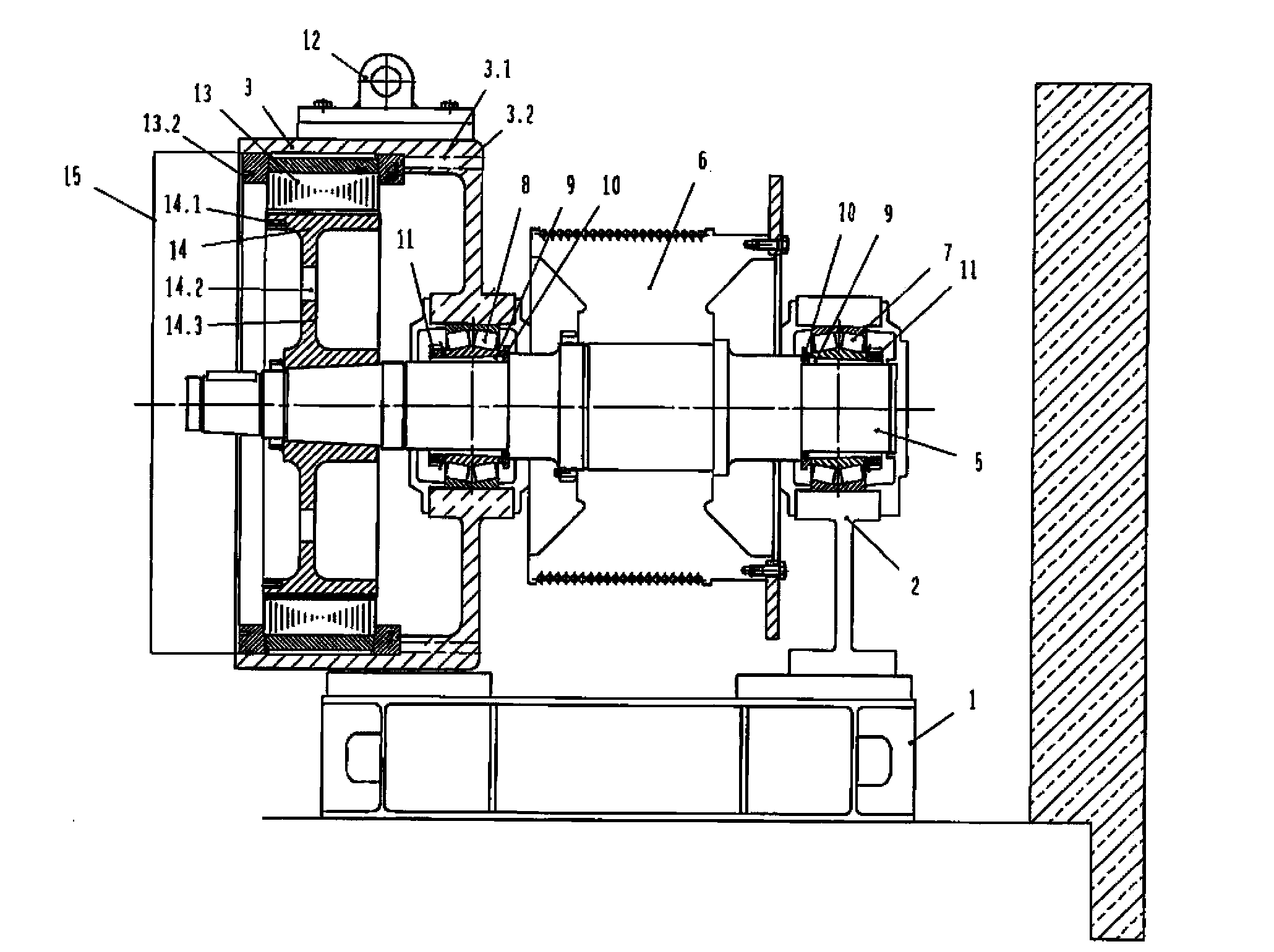
[0063] The gearless traction machine provided by the present invention, such as figure 1 As shown, it includes the traction machine base 1, the bearing support 2, the stator base 3, the main shaft 5, the traction wheel 6, the stator 13, the rotor 14, and the stator base cover plate 15, wherein the traction machine base 1 is fixed in the machine room On the girder 4, the part of the main shaft 5 located on the side of the stator 13 and the rotor 14 is supported by the bearing 7 installed in the bearing support 2 and the bearing 8 installed in the stator base 3, and the traction wheel 6 is installed on the bearing 7 and the bearing On the main shaft 5 between 8, the traction sheave 6 and the main shaft 5 can be connected by a key, or can be connected by a key plus an interference fit. This arrangement of supports on both sides of the t...


PUM


Abstract

The invention discloses a gearless traction machine. A stator pedestal and a bearing support are fixed on a traction machine base. A main shaft is supported through bearings arranged in the bearing support and the stator pedestal. A traction wheel is located on the main shaft between the stator pedestal and the bearing support. A rotor is installed on the other side of the main shaft, and a stator is fixed in the stator pedestal. A connection sleeve is arranged between the bearing and the main shaft, the connection sleeve is in conical surface match with the bearing, and the rotor is in conical surface match with the main shaft. In addition, threads are arranged at the end, located on the outer side of the rotor, of the main shaft. The invention further discloses an installation and maintenance device used for the gearless traction machine. Parts which are not assembled together of the gearless traction machine can be transported to a field for installation, large lifting devices such as a building tower crane are not needed, when some parts need to be repaired and replaced, due to the fact that the parts are more conveniently and detachably maintained and replaced, transportation cost is reduced and transportation difficulty is lowered, and the transportation flexibility and the carrying flexibility are improved. When the traction machine is updated and transformed, the parts which can be continuously used can be fully utilized, and updating cost is reduced.

Description

technical field [0001] The invention relates to a gearless traction machine of an elevator and its installation and maintenance device. The gearless traction machine is suitable for elevators of all specifications and models, especially for large (60kw-100kw) and super-large elevators. The installation and maintenance device for the gearless traction machine can be used for assembly and disassembly in a production workshop, and is especially suitable for direct assembly and disassembly at the elevator use site. Background technique [0002] The traction machine is the power equipment of the elevator, also known as the main engine of the elevator. Its function is to convey and transmit power to make the elevator run. The transmission is transmitted to the traction sheave, while the power of the gearless traction machine is directly transmitted to the traction sheave without passing through the intermediate reducer. [0003] Chinese patent CN1058572A discloses a transmissionl...

Claims


Application Information

Patent Timeline
IPC IPC(8): B66B11/04
Inventor 李洁张萍李磊
Owner SHANGHAI MITSUBISHI ELEVATOR CO LTD
Why Eureka
Try Eureka