Oilfield blowout control operation device and method

An operating device and oilfield technology, applied in earthwork drilling, wellbore/well components, sealing/isolation, etc., can solve the problems of high labor intensity, casualties, large space occupied by the double-arm structure, etc., and achieve displacement posture Strong adjustment ability, reduce blowout loss, and be conducive to the effect of automation

Active Publication Date: 2014-03-26
SHANGHAI JIAO TONG UNIV
View PDF7 Cites 8 Cited by
  • Summary
  • Abstract
  • Description
  • Claims
  • Application Information

AI Technical Summary

Problems solved by technology

At present, my country mainly relies on manual spraying operations, and casualties often occur
The Chinese patent No. 96227348.1 discloses an out-of-control blowout wellhead device for oil and gas wells, which can save manpower, has small structural size and low cost, and is more representative among similar products. The wellhead is too close, and the safety is not high; the operation process requires the cooperation of many people, and the operation is all manual, which is labor-intensive
The Chinese patent with the patent number CN101550812A discloses a relatively high degree of automation spraying operation device, which can realize functions including dismantling the waste wellhead and installing a well sealing device. The entire spraying operation is hydraulically controlled, but the device The degree of freedom of the centering and attitude adjustment mechanism is not enough, it is difficult to align the sealing device and the wellhead flange, and the double-arm structure used to fix rooting takes up a lot of space, which cannot meet the needs of spraying in complex sites

Method used


Image

  • Oilfield blowout control operation device and method
  • Oilfield blowout control operation device and method
  • Oilfield blowout control operation device and method

Examples


Embodiment Construction

[0022] Hereinafter, preferred embodiments of the present invention are given in conjunction with the drawings to illustrate the technical solutions of the present invention in detail.

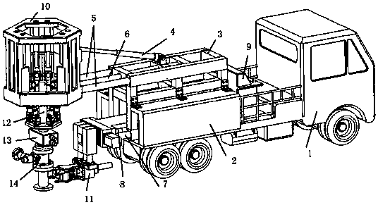
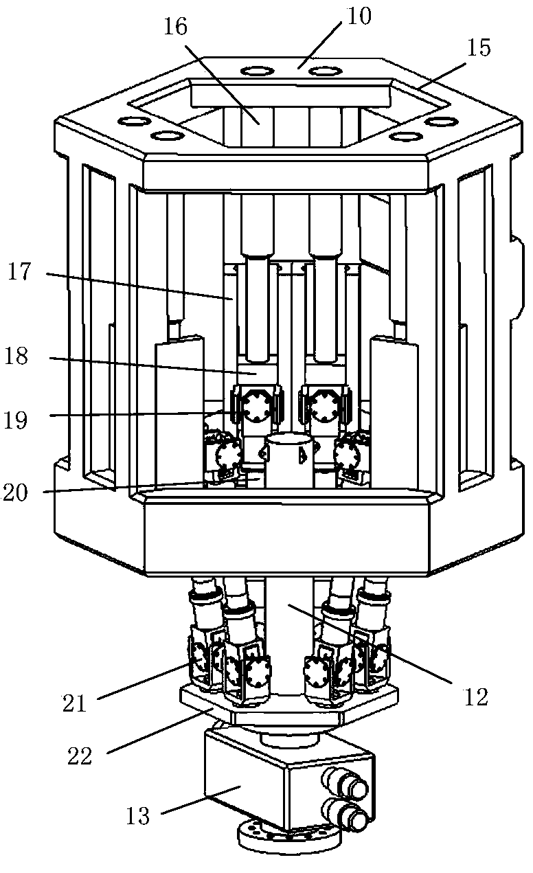
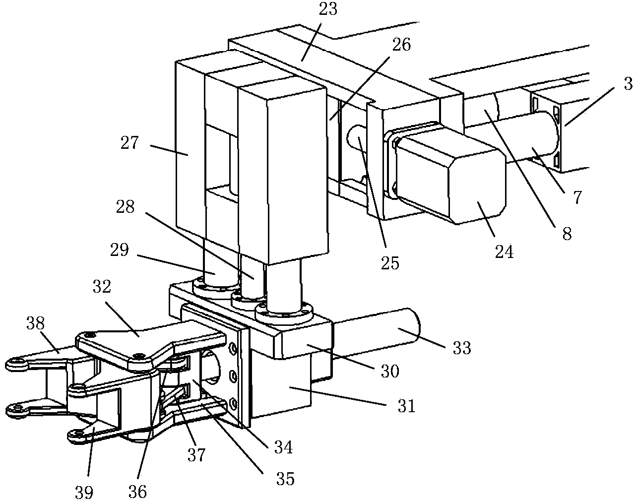
[0023] The present invention will be further described below in conjunction with specific embodiments: see attached figure 1 , figure 2 with image 3 , The oilfield rush injection operation device of the present invention includes a carrier vehicle 1, an auxiliary cylinder 4, an upper guide post guide sleeve 5, a lower guide post guide sleeve 7, a centering attitude adjustment device 10, an anchoring rooting device 11, and other auxiliary connections and drives Device; The carrier 1 is equipped with a frame 3, a hydraulic system 2 and a control console 9. The frame 3 is a steel structure welded and is a double-layer frame; the upper and lower four steel beams are installed with upper guides The post guide sleeve 5 and the lower guide post guide sleeve 7 are respectively matched with their respect...


PUM


Abstract

The invention discloses an oilfield blowout control operation device and method. The oilfield blowout control operation device comprises a carrier loader, an auxiliary cylinder, an upper guide post guide sleeve, a lower guide post guide sleeve, a centering and posture-adjusting device and an anchoring and rooting device. A frame, a hydraulic system and a console are installed on the carrier loader, the upper guide post guide sleeve is used for being connected with the centering and posture-adjusting device, the lower guide post guide sleeve is used for being connected with the anchoring and rooting device, and the tail ends of guide posts are connected rigidly through bolts. An upper driving cylinder is installed in the middle of the upper guide post guide sleeve, one end of the upper driving cylinder is fixed to the frame, and the other end of the upper driving cylinder is rigidly connected with the centering and posture-adjusting device. A lower driving cylinder is installed in the middle of the lower guide post guide sleeve, one end of the lower driving cylinder is fixed to the frame, and the other end of the lower driving cylinder is connected with the anchoring and rooting device. The oilfield blowout control operation device is high in automation degree, blowout can be controlled fast and effectively, and the safety guarantee is improved for field operators.

Description

Technical field [0001] The invention relates to a working device and a spray rush operation method thereof, in particular to an oil field spray rush operation device and a spray spray operation method thereof. Background technique [0002] After an oilfield blowout accident occurs, it is necessary to take immediate measures to control the blowout, otherwise the blowout out of control will have serious consequences. At present, our country mainly relies on manual spraying operations, and casualties often occur. The Chinese patent with the patent number 96227348.1 discloses a runaway blowout rush installation wellhead device for oil and natural gas wells, which can save manpower, has a small structure and a low cost. It is more representative among similar products, but the distance between personnel during operation The wellhead is too close, and the safety is not high; the operation process requires the cooperation of multiple people and full manual operation, which is labor-int...

Claims


Application Information

Patent Timeline
Patent Type & Authority Applications(China)
IPC IPC(8): E21B33/03
Inventor 何俊高峰
Owner SHANGHAI JIAO TONG UNIV
Why Eureka
Try Eureka